Other Parts Discussed in Thread: TMUX1511,
Dear Mr. Hall
On 8-16-19 you replied to my programming question about the AC excitation of the ADS1261 ADC. Due to priority changes, I have just now got back to this project. Please see below the pseudo-code command sequence you sent me with related questions.
WREG 02 48 / SINC 1, 1200SPS
WREG 03 61 / Enable 4-wire AC excitation
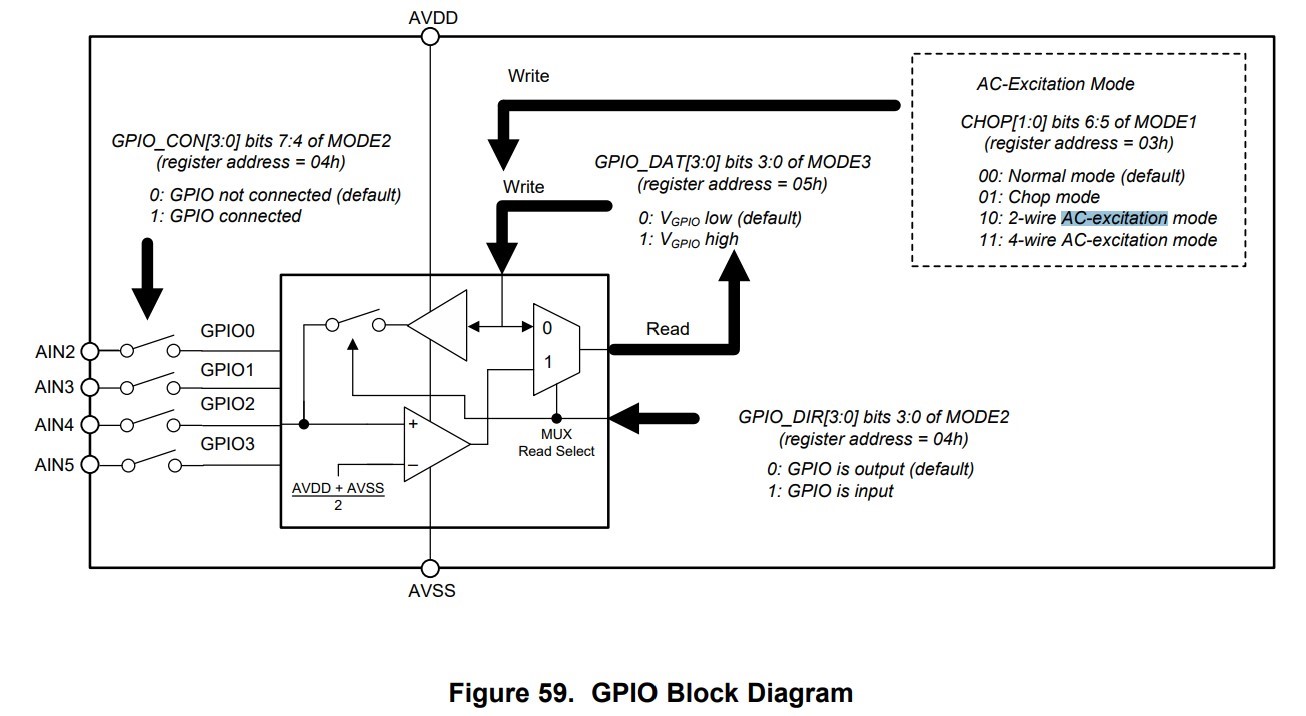
WREG 04 C0 / Configure AIN4 and AIN5 as GPIO outputs - by not enabling AIN2 and AIN3 this is an alternate way of performing 2-wire AC excitation.
QUESTION: Because 4-wire AC excitation is enabled, will enabling only AIN4 and AIN5 as GPIO outputs also enable AIN2 and AIN3 as GPIO outputs?
QUESTION: What do you mean by "by not enabling AIN2 and AIN3 this is an alternate way of performing 2-wire AC excitation"? Do you mean that if you were to enable 2-wire AC excitation, and configure AIN4 and AIN5 as GPIO outputs, AIN4 and AIN5 would become the drivers for the AC switching?
WREG 05 64 / Enable STATUS/CRC bytes and set GPIO2 HIGH.
QUESTION: In the AC-Excitation Timing Characteristics (FIG 7 page 14 in the ADS1261 data sheet), it shows ACX1 (GPIO2, AIN4) starting out low. By setting GPIO2 (AIN4, ACX1) high, does this mean that all ACX signals will be initialized opposite of what is shown in FIG 7? The reason I ask this is because I'm using 2-wire AC excitation and the TI TMUX1511 to due the AC switching. I have inadvertently connected !ACX1 and !ACX2 to the wrong switches. I therefore would like to flip the initial !ACX polarity. Can this be done?
WREG 06 0A / External AIN0 and AIN1 reference selected
QUESTION: It appears that an A written to the REF register (REG 6) will choose AIN2 as the positive reference input and the internal reference negative as the negative reference input. Is this correct or am I missing something?
WREG 10 00 / PGA enabled, gain of 1 V/V
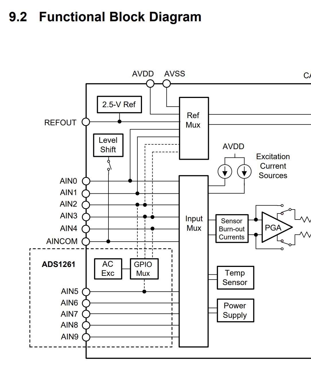
WREG 11 34 / Select AIN 2 and AIN3 as analog inputs
QUESTION: How can AIN 2 and AIN3 be used as inputs when they are being used for 4-wire excitation switching?


