This thread has been locked.

If you have a related question, please click the "Ask a related question" button in the top right corner. The newly created question will be automatically linked to this question.

ADS1018: ADS1018QDGSRQ1

Part Number: ADS1018

HI,

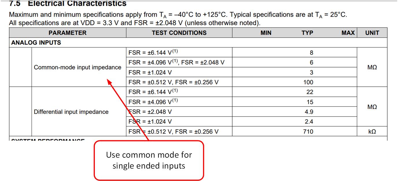
We are using analog  4 pin as single ended , let me know the leakage current for analog pin .

Considered 11 bit resolution is that correct. reference image attached.


  • Vanithkumar,

    I think that you should think in terms of “input impedance” as opposed to input leakage for the ADS1018. The inputs of this (and other delta-sigma) ADC is a switched capacitor input. This capacitor is relatively small and is switching at very high rate so that it acts like an impedance on the input. This impedance will be in parallel with your voltage divider and will introduce an error. Below is an exerpt from the data sheet showing the impedance.


    Notice that the impedance is given as a typical, so you have the following options to minimize error:

    1. You can assume the typical value is accurate and mathematically correct for the voltage divider error. This isn’t the best approach as the impedance can likely very +/-20%. However, applying the correction is better than not applying the correction and may be and acceptable error in many cases.
    2. Error can be minimized by reducing the voltage divider impedance. Typical input impedance greater than 3Mohm so a small external resistance will not impact your results by much.
    3. You can calibrate this error.
    4. See below a calculation and simulation that shows the error.

    I hope this helps.