This thread has been locked.

If you have a related question, please click the "Ask a related question" button in the top right corner. The newly created question will be automatically linked to this question.

ADS1299: ads1299. Bias out

Part Number: ADS1299

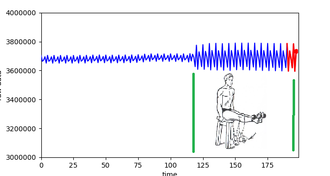
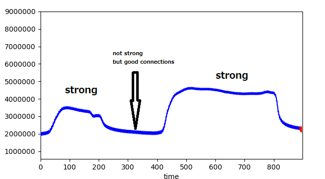
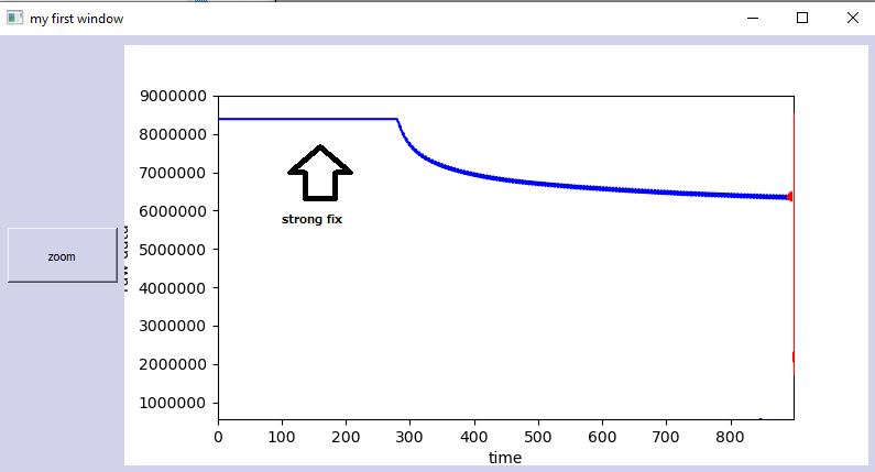
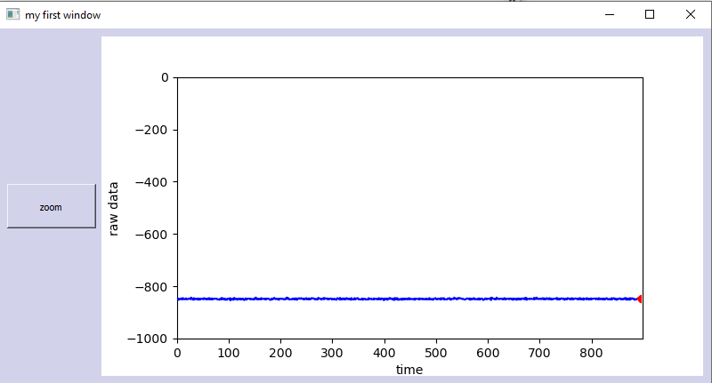
Hello. I have a little problem with the bias out signal in ADS1299. Bipolar voltage. For measurement, I use the scheme from manual ADS1299 - figure 73. When I measure the voltage between the electrode (on the head) and the reference electrode (left ear) I receive stable result -+0.5 µV. But when I connect bias out electrode (to right ear) my result significant grows up from 1 µV(+-0.5) to 12000 µV(+-30) between the electrode (on the head) and the reference electrode (left ear). I expected the opposite result, that with the bias electrode I will have a more stable result.

When i use the next register:

reg CONFIG3=0xEC

reg CONFIG2=0xD4

reg CONFIG1=0x96

reg 0x0D=0x00

reg 0x0E=0x01

reg 0x0F=0x00

reg 0x10=0x00
reg 0x11=0x00

reg 0x15=0x20

reg 0x17=0x00

reg CH1SET=0x08

the voltage between bias out electrode and ground in the board - "-1.24V". I try used different settings for the register but the result was similar.

I read BIOFAQ, but didn't find a similar problem. I know for what need BiasOUT, Biasinv, Biasin but this knowledge, not enough for understand - why when I connect bias out electrode to ear my measurement result grow up?

  • Hi Ildar,

    By chance, did you read this app note on RLD? 

    https://e2e.ti.com/support/data-converters/f/73/p/842529/3115361#3115361

    The body is being biased to a different voltage potential in order to cancel out the noise and ensure that the measurement is within the common-mode range of the PGA.

    What I assume you are seeing is a DC offset, and is ultimately not that important since what you're actually interested in measuring is the AC portion, the brain waves. is this DC offset changing over time, or is it stable?

    If the DC offset is changing over time, does it settle out after a period of time? 

  • Thank you, Alex, for the quick answer. Yes, I already read - "Improving Common-Mode Rejection Using the Right-Leg Drive Amplifier " and now start read again. I would add that I use an external battery for power supply. 

    When I measure EEG signal without bias I receive the next result (without any converting, 250 samples, the average value for 5 measurements)

    -49
    -51
    -52
    -51
    -47
    -46
    -49
    -50
    -51
    -49
    -46

     This signal i receive with bias connection

    1340320
    1339839
    1339890
    1340222
    1340965
    1341391
    1340968
    1340931
    1340739
    1340440
    1339879
    1339649
    1339922
    1339731
    1340133
    1340425
    1340199
    1340645
    1340837
    1340736

    Without bias I think that I receive more stable signal, it is strange

    when I made simulation and connected to each other reference electrode and EEG electrode (and connect bias electrode to both electrodes through a 3 kΩ resistor) I receive the next result

    3259749
    3259756
    3259755
    3259759
    3259783
    3259762
    3259747
    3259741
    3259752
    3259745

  • Hi Ildar,

    This is an interesting observation - it certainly seems that adding the series resistance reduced the noise.

  • Hello, Alex, sorry I still have the problem. Now checked different settings and made graphs.

    1. When I use bias out electrode - measurement depends on the connections legs and floor. When legs connect to the floor I have a big noise.

    2.When bias out register - OFF. (0x0D, 0x0E, 0x0F,0x10,0x11 = 00h)

    Bias out electrode is very sensitive. Every time when the bias electrode connects to the ear I receive a different result. In the photo lower you can see differences between strong fixation bias out electrode and not strong.

    3. 2.When bias out register - On (0x0D=01h, 0x0E, 0x0F,0x10,0x11 = 00h)

    Bias out electrode is very sensitive.How you can see in the photo lower when I connect biases out electrode with good fixation I receive saturation of the amplifier 

    same result when i use 2M, 1M, 500K, 100 K

    4. without bias electrode I receive a stable result. But this signal without useful information. without any frequency. It looks not correct.

    It is very strange - when i measure the voltage between biasout and GND in the board i have - 0.7 V. but should be 0


    Alex, Maybe I can send to you - my PCB board scheme and photo, electrical scheme, and program by email. I made board by recommendation TI, checked many times, but maybe some mistake there?

  • Hi Ildar,

    These results are due to changing electrode connection impedance, or changing how the patient is grounded. This is a dynamic electrical system, so seeing changing to electrical signals when there is a changing impedance in the feedback loop is not surprising. Similar for when the patient grounding (legs up or down) changes.  I recommend focusing on your digital filtering techniques if you would like to remove these motion artifacts.