This thread has been locked.

If you have a related question, please click the "Ask a related question" button in the top right corner. The newly created question will be automatically linked to this question.

ADS1115: ADC intermittently returning zero

Part Number: ADS1115
Other Parts Discussed in Thread: ISO1540,

I am using he ADS1115 behind an I2C isolator ISO1540. I am getting intermittent zero results. I am using a scope to verify the I2C signals, and all looks good.

I have had this issue with several applications so far. My current solution is to read it multiple times to get a non-zero value. Sometimes it returns with data on the first try, sometimes not after 20 consecutive readings.

My application is using an ST STM32G4 controller, but I have had issues before with Arduino test systems. The microcontroller side is 3.3v and the ADS side is 5v. My ADC voltage is close to 5.0V, but not near the 5.5V limit.

While I am sure the part works well, it won't in my applications.

  • John,

    Can you please post your scope shots of the I2C communications? It might help with the debug. Post a good reading and then post another reading with the conversion that reports a zero result. 

    My main concern is that the ADC is running 5V and that the microcontroller side is running 3.3V. If the pull up goes only to 3.3V, then the digital high might not be high enough to be read by the ADC. Normally you would use some sort of I2C voltage level translator between the two. 

    Regardless, the scope shot should show if the ADC ACKs the communication. 

    Joseph Wu

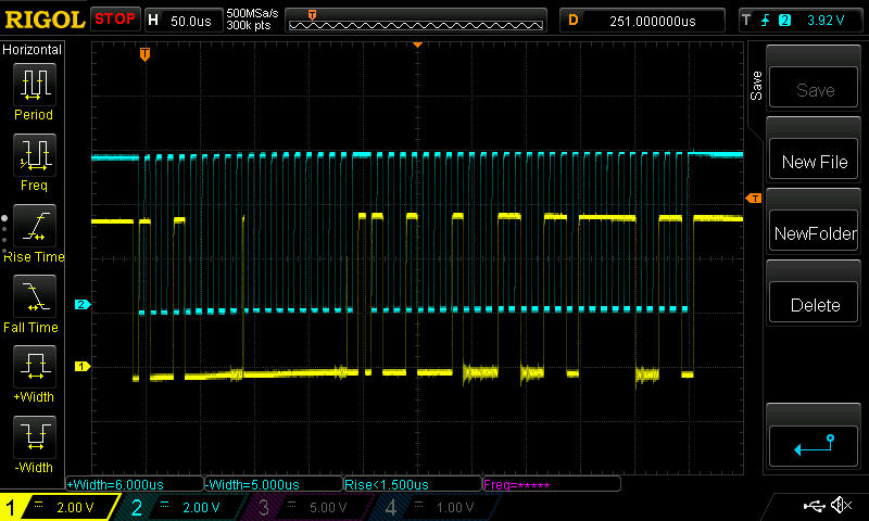
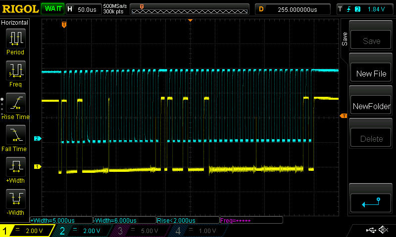
  • Here are some O-Scope shots of the 5v and 3.3v sides of the isolator.  The isolator is also acting as a voltage shifter.

    5V side with` good data

    3.3v side with good data

    5v side with zero data

    3.3v side with zero data

  • John,

    I'll need a little time to look this over. It looks like the 3.3V side of things is having a hard time pulling down on the SDA. However, that doesn't seem to be the problem.

    In the meantime, what do you have programmed into the configuration register?

    Joseph Wu

  • Here is the driver function:

    uint16_t GetAds1115Values(ADS1115_HandleTypeDef *hdev, uint8_t channel, uint16_t m_gain, uint8_t *count)
    {
    uint8_t ADSwrite[6];
    int16_t result_word;
    uint8_t retries = 5;
        do{
                ADSwrite[0] = 0x01;
                switch(channel)
                {
                        case(0):
                        ADSwrite[1] = 0xC3; // 11000011
                        break;
                        case(1):
                        ADSwrite[1] = 0xD3; // 11010011
                        break;
                        case(2):
                        ADSwrite[1] = 0xE3; // 11100011
                        break;
                        case(3):
                        ADSwrite[1] = 0xF3; // 11110011
                        break;
                }

    // ADSwrite[2] = 0x03; // 00000011 8 SPS
    // ADSwrite[2] = 0x23; // 10000011 16 SPS
    // ADSwrite[2] = 0x43; // 10000011 32 SPS
    // ADSwrite[2] = 0x63; // 01100011 64 SPS
    ADSwrite[2] = 0x83; // 10000011 128 SPS
    // ADSwrite[2] = 0xC3; // 11000011 475 SPS
    // ADSwrite[2] = 0xE3; // 11100011 860 SPS
    HAL_I2C_Master_Transmit(hdev->hi2c, hdev->addr, ADSwrite, 3, 100);
    HAL_Delay(60);
    ADSwrite[0] = 0x00;
    HAL_I2C_Master_Transmit(hdev->hi2c, hdev->addr, ADSwrite, 1, 100);
    HAL_I2C_Master_Receive(hdev->hi2c, hdev->addr, ADSwrite, 2, 100);
    result_word = (ADSwrite[0] << 8 | ADSwrite[1]);


            if( result_word == 0)
            {
                    retries--;
                    HAL_Delay(10);
            }


    }while(result_word==0 && retries);


    if(result_word < 0 ) //can go slightly negative around 0
    {
            result_word = 1;
    }

    *count = retries;

    return(result_word);

    }

    Here is the output

    Channel 0 value 13292, 23.814777 volts, count = 3
    Channel 1 value 13107, 23.483320 volts, count = 3
    Channel 2 value 13207, 23.662487 volts, count = 1
    Channel 3 value 20416, 5.104000 volts, count = 5

    Channel 0 value 13291, 23.812986 volts, count = 4
    Channel 1 value 13107, 23.483320 volts, count = 1
    Channel 2 value 13209, 23.666069 volts, count = 2
    Channel 3 value 0, 0.000000 volts, count = 0 ****

    Channel 0 value 13288, 23.807611 volts, count = 2
    Channel 1 value 13107, 23.483320 volts, count = 3
    Channel 2 value 13207, 23.662487 volts, count = 2
    Channel 3 value 20414, 5.103500 volts, count = 2

    Channel 0 value 0, 0.000000 volts, count = 0 ****
    Channel 1 value 13106, 23.481529 volts, count = 5
    Channel 2 value 13208, 23.664278 volts, count = 4
    Channel 3 value 20416, 5.104000 volts, count = 5

    Channel 0 value 13290, 23.811195 volts, count = 5
    Channel 1 value 13106, 23.481529 volts, count = 4
    Channel 2 value 13209, 23.666069 volts, count = 3
    Channel 3 value 20416, 5.104000 volts, count = 5

    Channel 0 value 13291, 23.812986 volts, count = 5
    Channel 1 value 13106, 23.481529 volts, count = 4
    Channel 2 value 13208, 23.664278 volts, count = 5
    Channel 3 value 20418, 5.104500 volts, count = 4

    Channel 0 value 13290, 23.811195 volts, count = 5
    Channel 1 value 13106, 23.481529 volts, count = 2
    Channel 2 value 13207, 23.662487 volts, count = 3
    Channel 3 value 20417, 5.104250 volts, count = 3

    Channel 0 value 0, 0.000000 volts, count = 0 ****
    Channel 1 value 13107, 23.483320 volts, count = 5
    Channel 2 value 0, 0.000000 volts, count = 0 ****
    Channel 3 value 20416, 5.104000 volts, count = 3

    Channel 0 value 13290, 23.811195 volts, count = 4
    Channel 1 value 13106, 23.481529 volts, count = 4
    Channel 2 value 13207, 23.662487 volts, count = 5
    Channel 3 value 20416, 5.104000 volts, count = 5

    Channel 0 value 13291, 23.812986 volts, count = 4
    Channel 1 value 13110, 23.488695 volts, count = 5
    Channel 2 value 13208, 23.664278 volts, count = 5
    Channel 3 value 20417, 5.104250 volts, count = 4

    Channel 0 value 13292, 23.814777 volts, count = 3
    Channel 1 value 13106, 23.481529 volts, count = 5
    Channel 2 value 0, 0.000000 volts, count = 0 ****
    Channel 3 value 20417, 5.104250 volts, count = 5

    Channel 0 value 13291, 23.812986 volts, count = 4
    Channel 1 value 13106, 23.481529 volts, count = 4
    Channel 2 value 13207, 23.662487 volts, count = 5
    Channel 3 value 20413, 5.103250 volts, count = 5

    You can see where the count is not 5, A zero count is a retry failure.

  • John,

    Based on the code that you've provided, it looks like you have the device set up to measure the four inputs single-ended. The FSR is set to the ±4.096V range, with the device in single-shot conversion mode, the data rate at 128SPS, and the comparator disabled.

    First, I would leave the device in single-shot conversion mode. Using continuous conversion mode and switching channels can be difficult to keep track of channel data. Writing a configuration does not set the configuration until after the conversion in progress is completed. As the data is collected, the controller may lose track of which data was taken for which channel.

    I'm not sure, but this could be a problem with the not giving enough time for the conversion to complete. Normally, after starting the conversion, I would have the controller wait a set time period before starting the read. This time would be:

    (1/(data period) + 10%) + 20us

    The 10% is for the variation in the device's internal clock and 20us would be to allow the device to wake up from a power-down state. If the device is set to 128SPS, the time period would be 862us.

    To see if this is the problem, you could do one of two things that you can try separately. First you could add a this delay to before the read of the conversion data. This would allow the device time to complete the conversion. Second, you could change the data rate to something faster. If you set the data rate to 475SPS and this problem happened less frequently, or went away this would likely be the culprit.

    You could also use a logic analyzer to check the time between the conversion start to the conversion read and see if the zero data corresponded with shorter times between the communication.

    Regardless, you should be able to test this quickly to see if it helps.


    Joseph Wu

  • Thank yo for the reply.  I do have a 60mS delay between setting the configuration and reading the data register (HAL_Delay(60) ).  I think this should be enough for any datarate.  

    I will try faster data rates to see if this helps.  

    The board is already built, and is very tight in that area.  I don't know if I can get a line on the comparator output to watch for conversion completion.  I might be able to get it under a microscope to put a wire on it.  Maybe Sunday I can attack this.

  • John,

    One thing about the data rate that I wanted to point out. The ADS1115 is a delta-sigma (or oversampling) type of data converter. During the data period, the ADC samples the input voltage at a rate of about 250kHz. All of these samples are collected to produce one data point. 

    If the device is set to a data rate of 128SPS, then you will need to wait the entire data period to get the data point. 


    Joseph Wu

  • With a datarate of 475SPS and 60mS wait time I get this:


    Channel 0 value 13462, 24.119360 volts, count = 5
    Channel 1 value 13280, 23.793278 volts, count = 1
    Channel 2 value 0, 0.000000 volts, count = 0 ****
    Channel 3 value 0, 0.000000 volts, count = 0 ****

    Channel 0 value 13463, 24.121153 volts, count = 4
    Channel 1 value 13279, 23.791487 volts, count = 5
    Channel 2 value 0, 0.000000 volts, count = 0 ****
    Channel 3 value 0, 0.000000 volts, count = 0 ****

    Channel 0 value 13463, 24.121153 volts, count = 3
    Channel 1 value 13281, 23.795069 volts, count = 5
    Channel 2 value 0, 0.000000 volts, count = 0 ****
    Channel 3 value 0, 0.000000 volts, count = 0 ****

    Channel 0 value 13461, 24.117569 volts, count = 5
    Channel 1 value 0, 0.000000 volts, count = 0 ****
    Channel 2 value 0, 0.000000 volts, count = 0 ****
    Channel 3 value 0, 0.000000 volts, count = 0 ****

    Channel 0 value 13460, 24.115778 volts, count = 5
    Channel 1 value 13281, 23.795069 volts, count = 5
    Channel 2 value 0, 0.000000 volts, count = 0 ****
    Channel 3 value 0, 0.000000 volts, count = 0 ****

    Channel 0 value 13460, 24.115778 volts, count = 3
    Channel 1 value 13277, 23.787903 volts, count = 4
    Channel 2 value 0, 0.000000 volts, count = 0 ****
    Channel 3 value 0, 0.000000 volts, count = 0 ****

    Channel 0 value 13459, 24.113985 volts, count = 4
    Channel 1 value 13276, 23.786112 volts, count = 4
    Channel 2 value 0, 0.000000 volts, count = 0 ****
    Channel 3 value 0, 0.000000 volts, count = 0 ****

    Channel 0 value 13460, 24.115778 volts, count = 5
    Channel 1 value 13275, 23.784319 volts, count = 4
    Channel 2 value 0, 0.000000 volts, count = 0 ****
    Channel 3 value 0, 0.000000 volts, count = 0 ****

    With a datarate of 860SPS, I get this


    Channel 0 value 13437, 24.074570 volts, count = 2
    Channel 1 value 13250, 23.739529 volts, count = 1
    Channel 2 value 0, 0.000000 volts, count = 0 ****
    Channel 3 value 0, 0.000000 volts, count = 0 ****

    Channel 0 value 13437, 24.074570 volts, count = 4
    Channel 1 value 0, 0.000000 volts, count = 0 ****
    Channel 2 value 0, 0.000000 volts, count = 0 ****
    Channel 3 value 0, 0.000000 volts, count = 0 ****

    Channel 0 value 0, 0.000000 volts, count = 0 ****
    Channel 1 value 13248, 23.735945 volts, count = 5
    Channel 2 value 0, 0.000000 volts, count = 0 ****
    Channel 3 value 0, 0.000000 volts, count = 0 ****

    Channel 0 value 0, 0.000000 volts, count = 0 ****
    Channel 1 value 0, 0.000000 volts, count = 0 ****
    Channel 2 value 0, 0.000000 volts, count = 0 ****
    Channel 3 value 0, 0.000000 volts, count = 0 ****

    Channel 0 value 13437, 24.074570 volts, count = 2
    Channel 1 value 0, 0.000000 volts, count = 0 ****
    Channel 2 value 0, 0.000000 volts, count = 0 ****
    Channel 3 value 0, 0.000000 volts, count = 0 ****

    Channel 0 value 13437, 24.074570 volts, count = 2
    Channel 1 value 13250, 23.739529 volts, count = 4
    Channel 2 value 13348, 23.915112 volts, count = 4
    Channel 3 value 0, 0.000000 volts, count = 0 ****

    Channel 0 value 0, 0.000000 volts, count = 0 ****
    Channel 1 value 0, 0.000000 volts, count = 0 ****
    Channel 2 value 0, 0.000000 volts, count = 0 ****
    Channel 3 value 0, 0.000000 volts, count = 0 ****

    I am going to try to run it at 3.3v instead of 5.

  • Looks like the ADS1115 does not like 5v.  Here is the result on 3.3v at the highest datarate:

    Channel 0 value 13405, 24.017237 volts, count = 5
    Channel 1 value 13925, 24.948900 volts, count = 5
    Channel 2 value 13953, 24.999067 volts, count = 5
    Channel 3 value 13413, 3.353250 volts, count = 5

    Channel 0 value 14042, 25.158525 volts, count = 5
    Channel 1 value 13928, 24.954275 volts, count = 5
    Channel 2 value 13953, 24.999067 volts, count = 5
    Channel 3 value 13411, 3.352750 volts, count = 5

    Channel 0 value 14044, 25.162107 volts, count = 5
    Channel 1 value 13929, 24.956066 volts, count = 5
    Channel 2 value 13955, 25.002649 volts, count = 5
    Channel 3 value 13413, 3.353250 volts, count = 5

    Channel 0 value 14045, 25.163900 volts, count = 5
    Channel 1 value 13928, 24.954275 volts, count = 5
    Channel 2 value 13956, 25.004442 volts, count = 5
    Channel 3 value 13413, 3.353250 volts, count = 5

    Channel 0 value 14043, 25.160316 volts, count = 5
    Channel 1 value 13929, 24.956066 volts, count = 5
    Channel 2 value 13955, 25.002649 volts, count = 5
    Channel 3 value 13414, 3.353500 volts, count = 5

    Channel 0 value 14045, 25.163900 volts, count = 5
    Channel 1 value 13929, 24.956066 volts, count = 5
    Channel 2 value 13956, 25.004442 volts, count = 5
    Channel 3 value 13413, 3.353250 volts, count = 5

    Channel 0 value 14044, 25.162107 volts, count = 5
    Channel 1 value 13930, 24.957859 volts, count = 5
    Channel 2 value 13955, 25.002649 volts, count = 5
    Channel 3 value 13414, 3.353500 volts, count = 5

    Channel 0 value 14044, 25.162107 volts, count = 5
    Channel 1 value 13931, 24.959650 volts, count = 5
    Channel 2 value 13955, 25.002649 volts, count = 5
    Channel 3 value 13413, 3.353250 volts, count = 5

    Channel 0 value 14046, 25.165691 volts, count = 5
    Channel 1 value 13932, 24.961441 volts, count = 5
    Channel 2 value 13955, 25.002649 volts, count = 5
    Channel 3 value 13414, 3.353500 volts, count = 5

    I may try 4.50v so I can use the 4.096 Vref

  • Looks like it also likes 4.5v, but it always misses the very first conversion:

    Compile information
    Jun 26 2020
    13:20:09
    ../Core/Src/main.c

    Channel 0 value 13398, 24.004694 volts, count = 4
    Channel 1 value 13218, 23.682196 volts, count = 5
    Channel 2 value 13321, 23.866735 volts, count = 5
    Channel 3 value 18102, 4.525500 volts, count = 5

    Channel 0 value 13401, 24.010069 volts, count = 5
    Channel 1 value 13218, 23.682196 volts, count = 5
    Channel 2 value 13323, 23.870319 volts, count = 5
    Channel 3 value 18108, 4.527000 volts, count = 5

    Channel 0 value 13402, 24.011860 volts, count = 5
    Channel 1 value 13221, 23.687571 volts, count = 5
    Channel 2 value 13320, 23.864944 volts, count = 5
    Channel 3 value 18103, 4.525750 volts, count = 5

    Channel 0 value 13402, 24.011860 volts, count = 5
    Channel 1 value 13219, 23.683987 volts, count = 5
    Channel 2 value 13322, 23.868528 volts, count = 5
    Channel 3 value 18104, 4.526000 volts, count = 5

    Channel 0 value 13401, 24.010069 volts, count = 5
    Channel 1 value 13220, 23.685778 volts, count = 5
    Channel 2 value 13322, 23.868528 volts, count = 5
    Channel 3 value 18106, 4.526500 volts, count = 5

    Channel 0 value 13404, 24.015444 volts, count = 5
    Channel 1 value 13219, 23.683987 volts, count = 5
    Channel 2 value 13325, 23.873903 volts, count = 5
    Channel 3 value 18105, 4.526250 volts, count = 5

    Channel 0 value 13401, 24.010069 volts, count = 5
    Channel 1 value 13221, 23.687571 volts, count = 5
    Channel 2 value 13322, 23.868528 volts, count = 5
    Channel 3 value 18107, 4.526750 volts, count = 5

    Channel 0 value 13401, 24.010069 volts, count = 5
    Channel 1 value 13221, 23.687571 volts, count = 5
    Channel 2 value 13322, 23.868528 volts, count = 5
    Channel 3 value 18110, 4.527500 volts, count = 5

    Channel 0 value 13403, 24.013653 volts, count = 5
    Channel 1 value 13219, 23.683987 volts, count = 5
    Channel 2 value 13320, 23.864944 volts, count = 5
    Channel 3 value 18106, 4.526500 volts, count = 5

    Channel 0 value 13404, 24.015444 volts, count = 5
    Channel 1 value 13218, 23.682196 volts, count = 5
    Channel 2 value 13321, 23.866735 volts, count = 5
    Channel 3 value 18106, 4.526500 volts, count = 5

    Channel 0 value 13401, 24.010069 volts, count = 5
    Channel 1 value 13218, 23.682196 volts, count = 5
    Channel 2 value 13322, 23.868528 volts, count = 5
    Channel 3 value 18106, 4.526500 volts, count = 5

  • John,


    The output of the device shouldn't really be affected by the supply voltage, especially if the supply is within the normal operating range. Because you have some sort of isolation, I'm wondering if you have a common ground between your sensor inputs and the ADC.

    Can you share a schematic? It may help to know how you have this test set up. Along with the schematic, I'd like to know what you have connected to the ADC inputs of the device.


    Joseph Wu

  • Here is the isolated analog  section.  I am using an isolated DC-DC converter to drive it.  The analog inputs to the section are from a 48v system, which does not share a ground with the main system.  The solution I am using now is adding 100 ohm load to the output of the DC-DC converter to load it better for regulation, and place a 1N4148 diode between C160 and C156 for a 0.6v drop.  This gives me about 4.5V on the ADS and it works nearly flawlessly.

    ISO_Analog_Section.pdf

  • John,


    I've got a test for you to try. As I mentioned in the last post, the operation of the device shouldn't really be affected by the supply voltage. Now that I've seen your schematic, I would try a modification.

    On your schematic, you have L7 and L8 inductors connected to the supply and ground of the device. I would remove them and replace them with shorts. I generally avoid inductors with ADCs. In the ADC, there are digital currents running through the device. While the average isn't much, they can be instantaneously large, which is why we use bypass capacitors at the supply. Digital currents with inductors will spike the voltage, because of the large L(dI/dt).

    With large spikes in the supply voltage, there's a chance that you can create such a large periodic spike that this could trip the power-on-reset in the device. This could reset the device. If this were the case, this would explain the reason that the device is occasionally reading 0V. The 0V reading would be the first reading from the device after power up. Normally, I would have expected that a read of the configuration register would have just given the previous ADC conversion, but I think that you might just be resetting the part.

    Again, short both L7 and L8 and run the tests over supply again. I think this may be the problem. I have seen cases in the past where an inductor in the supply or an inductor connection to ground have caused this kind of reset.

    Joseph Wu

  • Joseph,

    It looks like that may have fixed it.  I get no read failures and no I2C bus errors.  I will keep testing, but I believe this is the answer.

  • John,

    Thanks. I've seen that sort of thing before. I'll close out this post for now, but if you have further questions, you can post back and we can continue to work on this issue (or any other issues).

    Joseph Wu