This thread has been locked.

If you have a related question, please click the "Ask a related question" button in the top right corner. The newly created question will be automatically linked to this question.

ADS1262EVM-PDK: ADS1262EVM-PDK Poor Performance

Part Number: ADS1262EVM-PDK

We are planning to develop a 6 1/2 to 7 digit universal process indicator with RTD, Thermocouple and other analogue inputs (Ohms,mVolt,Volt,mAmps).So we decided to go for 32 bit ADC. After referring to the datasheet we thought ADS1262 might be suitable for our application. We purchased a ADS1262EVM-PDK kit .we started testing on the kit and found the results of the ADC's performance very poor. The details of the test results and our requirement are given below. Suggest best method to achieve our requirement with maximum number of noise free counts.


-------------------------------------------------------------------------------------------------------------------------------------------------------

Readings for 390E RTD input (Connections as per ADS1262EVM-PDK User's Guide Section 2.6.2 Pg No:15 Fig:11)

-------------------------------------------------------------------------------------------------------------------------------------------------------

IDAC Current                     : 250uA

Data Rate                            : 20SPS

Filter                                      : Sinc4

Vref                                       : Voltage Across Ain4-5 (2V)

Gain                                       : 16

Chop                                     : Enabled

IDAC Rotation                    : Enabled

ADC count Variation       : 1718039712-1718073508


Noise free count is 17180 the next digit varies +/- 2 counts.

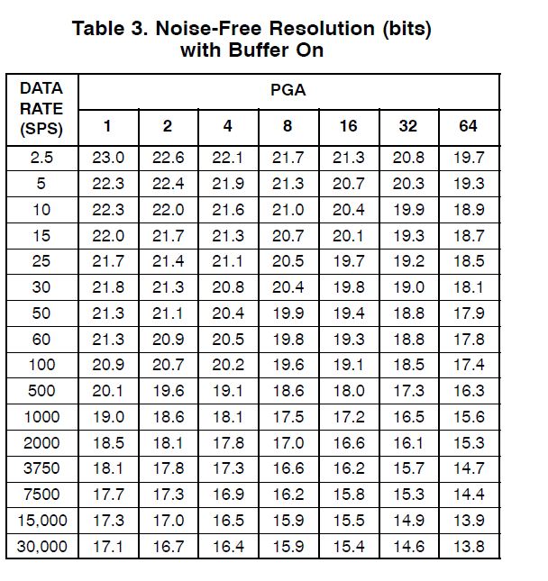
Effective Number of Bits mentioned in datasheet for gain 16 is 24.6

Noise free bits for gain 16 is 22.1 which is not achieved practically.

Our Requirement is noise free 800000 counts.

How can we solve this problem? Suggest best method to achieve the required counts.

-----------------------------------------------------------------------------------------------------------------------------------------------------

Readings for 2V input     (Connections as per ADS1262EVM-PDK User's Guide Section 2.6.3 Pg No:16 Fig:12)

-----------------------------------------------------------------------------------------------------------------------------------------------------

Vref                                       : Internal 2.5V

Data Rate                            : 20sps

Filter                                      : Sinc4

Gain                                       : 1

Bias Polarity                        : Pull Up mode

AINCOM                              : LEVEL SHIFT ON

Chop                                     : Enabled

ADC count Variation       : 1726703349-1726829883


Noise free count is 1726 the next digit varies 1 count.

Effective Number of Bits mentioned in datasheet for gain 1 is 25.4

Noise free bits for gain 16 is 22.9 which is not achieved practically.

Our Requirement is noise free 400000 counts

How can we solve this problem? Suggest best method to achieve the required counts.

--------------------------------------------------------------------------------------------------------------------------------------------------------


Similarly for 80mV input we require noise free 80000 counts.

  • Hi Venkatavel,

    Can you short the ADC inputs together to a mid-supply voltage and see if you are getting the datasheet noise performance at various filter, data rate and gain settings? This will tell you if there is an issue with the ADC or if the noise is coming from another source. You can also test global chop on and off. Please post a table of your results

    Also, can you take lots of samples for each measurement you described in your last post and send out the raw data? Or, you can also find the standard deviation of this dataset which will give you the RMS noise. RMS noise is generally a better indication of the system performance, as the NFB numbers provided in an ADC's datasheet assume the full-scale range is maximized. You can see in Table 2 in the ADS1262 datasheet that VREF = 5V, which yields a full-scale range (FSR) of 10V at gain = 1 (since full scale extends from -VREF/gain to +VREF/gain). But if you are using a 2V or 2.5V reference, then the FSR is only 4V or 5V, respectively. This reduces your maximum signal range, though the ADC noise will be the same, resulting in lower NFB compared to the specs / conditions in the datasheet. And if your input signal is not the same as the VREF, then you are only using a percentage of the FSR, further reducing the available dynamic range / NFB. So it makes more sense to look at this in terms of RMS (or PP) noise performance.

    You should note that at the dynamic range you are after (400k or 800k counts), you will likely need to calibrate the entire system to remove any offsets and other sources of noise. You will most definitely need a gain calibration as well, likely at the system level.

    Please run these few tests and let me know the results.

    -Bryan

  • Hi Bryan,

    Thank you for your speedy reply Bryan.I have taken the reading as you have said.I have attached the excel sheet of the readings.

    Vref                                       : Internal 2.5V

    Data Rate                            : 20sps

    Filter                                      : Sinc1

    Gain                                       : 1

    Bias Polarity                        : Pull Up mode

    AINCOM                              : LEVEL SHIFT ON

    Chop                                     : Enabled

    ADC count Variation       : -663 to 1283

    Input Shorted.

    In your mail you have mentioned  "You can see in Table 2 in the ADS1262 datasheet that VREF = 5V, which yields a full-scale range (FSR) of 10V at gain = 1 (since full scale extends from -VREF/gain to +VREF/gain). But if you are using a 2V or 2.5V reference, then the FSR is only 4V or 5V, respectively. "

    In the ADS1262EVM-PDK kit there is only internal Vref of 2.5V. How can i Select 5V reference externally.Moreover I think Internal 2.5V ref will be more stable than external 5V.

    I want to know the NFB for Internal 2.5V Reference.

    In the datasheet  Table 1. ADC1 Noise in μVRMS (μVPP) at TA = 25°C, VAVDD = 5 V, VAVSS = 0 V, VREF = 2.5 V and

    Table 2. ADC1 ENOB (Noise Free Bits) at TA = 25°C, VAVDD = 5 V, VAVSS = 0 V, VREF = 5 V.

    I have a question that why ENOB and Noise Free Bits is not given for VREF=2.5V.

    Warm Regards,

    Venkatavel.

    ADS1262_Input_Short.xlsx

  • Hi Bryan,

     I am attaching the readings of ADS1262EVM-PDK with input short for 20 sps ,different gains and different filter.Please give us a solution

    ADS1262_Input_Short_Sinc1.xlsxADS1262_Input_Short_Sinc2.xlsxADS1262_Input_Short_Sinc3.xlsxADS1262_Input_Short_Sinc4.xlsxADS1262_Input_Short_FIR.xlsx

    Warm Regards,

    Venkatavel

  • Hi Venkatavel,

    Thanks for sending these files, I summarized the data in the table below. Looks like the noise values are not exactly the datasheet values, but they are usually within 10-15nV. Quite honestly, vibrations in the room in which you are testing, or even breathing heavily on the board, could cause such minor disturbances.

    So I would conclude that the ADS1262 is operating properly and providing the requisite noise performance.

    Table 1: ADS1262 EVM at 20 SPS, chop on

    Filter type Noise value (nVRMS) G = 1 G = 2 G = 4 G = 8 G = 16 G = 32
    Sinc1 Calculated 367.4 177.3 100.4 55.8 39.0 34.8
    Datasheet 336.0 167.0 85.0 49.0 33.0 26.0
    Sinc2 Calculated n/a 162.9 86.5 49.3 37.5 32.2
    Datasheet 270.0 136.0 70.0 39.0 28.0 21.0
    Sinc3 Calculated 296.0 155.0 78.7 45.6 34.4 26.6
    Datasheet 237.0 124.0 67.0 35.0 24.0 20.0
    Sinc4 Calculated 276.0 144.6 70.1 51.4 37.2 n/a
    Datasheet 229.0 113.0 60.0 34.0 22.0 17.0

    You can use an external VREF with the ADS1262 EVM e.g. the REF5050, if you choose. You can make these selections in the ADCPro GUI. An external VREF will generally be lower noise and lower drift compared to the internal VREF.

    The ADS1262 noise was characterized using the internal VREF because with inputs shorted, there is no injected noise from the VREF. So it is just easier to use the internal VREF for these measurements.

    The effective resolution / noise-free bits are calculated using the maximum VREF voltage as this maximizes the resulting dynamic range. Please note that the NFB values are therefore calculated assuming a 10V full-scale range (since VREF = 5V). If your system input signal is smaller, then your NFB will be reduced. But this is not necessarily a bad thing, since you are probably targeting a specific noise level in these applications.

    -Bryan

  • Hi Bryan,

              How to calculate Vrms from Raw counts.Can you specify how many NFB can be achieved for Vref=2.5V.

    Regards,

    Venkatavel.


  • Hi Bryan,

          Our requirement for RTD input of 390E is noise free 800,000 counts(+/-1 Count Variation).

           Our requirement for Thermocouple 80mV input is noise free 80,000 counts.

          How can we achieve this count with internal 2.5V reference.Data update speed is 20sps.

          What changes can be done in hardware or software in order to achieve this count.Please suggest the best method.

           We are also using other TI ADC like ADS1230,ADS1232 and ADS1256.Accidentally  I compared the NFB of ADS1256 and ADS1262 and found out that NFB for both ADC is almost same.

           I am attaching the NFB details of both ADC.


    Warm Regards ,

                  Venkatavel.

  • Hi Venkatavel,

    I would not consider your system in terms of noise-free bits, but in terms of absolute noise (nVRMS or nVPP). You can learn more about why this makes sense from our Precision Labs modules on noise (modules 5.2-5.4): https://training.ti.com/zh-tw/ti-precision-labs-adcs. Specifically Module 5.4 provides an example that is similar to what you are trying to do, albeit with a load cell. But you can apply the same principles to a temperature measurement.

    Most importantly, to understand the noise you need, you need to know the maximum output signal for each sensor (RTD and TC). Please review this information and let me know if you have further questions.

    -Bryan