This thread has been locked.

If you have a related question, please click the "Ask a related question" button in the top right corner. The newly created question will be automatically linked to this question.

ADS8860: Interfacing ADS8860 with ESP32 micro-processor

Part Number: ADS8860
Other Parts Discussed in Thread: OPA320, REF6033

Dear Sir, 

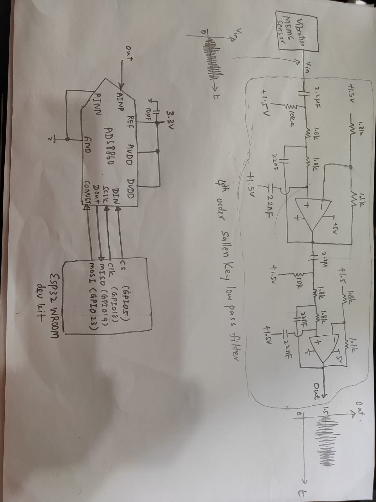
I would like to know how to interface with MEMs vibration sensor (ADXL1002z) and ADS8860 single ended 16 bits ADC, and micro-processor (ESP32). Please refer to below schematic diagram for my current interface between ADS8860 with sensors and processor. Could you help me answer following questions?

Q1. Do I need to add buffer between MEMs sensor output and filter?

Q2. Can I directly connect my filter output to AINP pin of ADS8860 and grounded the AINN pin of ADS8860?

Q3. Can I give +3.3V to "REF", "AVDD" and "DVDD" of ADS8860?

Q4. If I use 4 wire connection, do following connection correct from ADS8860 to ESP32 ? 

  • DIN > CS
  • SCLK > CLK
  • DOUT > MISO
  • DIN > MOSI

Thanks,

Peter

  • Hello Peter,

    Welcome to the TI E2E community.

    Q1:  This is really a question for the manufacturer of the ADXL1002z sensor.  Looking at the datasheet for the MEMs, it appears that you may need to add a buffer.  If you can still add one, I would suggest adding a buffer since this will clearly meet the requirements for the  MEMs sensor.

    Q2:  No, the input to the ADS8860 will require an input RC filter as well as a low output impedance amplifier to support 1MSPS.  Please take a look at Figure 3 in the ADS8860 datasheet for a recommended amplifier and RC filter.  If the sallen key filter uses the OPA320, then you can connect the output of the sallen-key filter to the RC filter and ADS8860.

    Q3:  You can if your maximum sample rate is much lower than 1MSPS (the exact number depends on the output impedance of the 3.3V supply).  In general, to get datasheet performance, you need to use a good, low output impedance, reference for the REFin.  The REF6033 will provide excellent performance and allow full datasheet performance at 1MSPS.

    Q4:  DIN is only used for data when using Daisy Chain mode.  There are multiple options to interface the ADS8860, but the simplest is to use 3-wire mode as shown in Figure 1 of the datasheet.  In this case, make the following connections.

    DIN -> 3.3V (connect this pin high)

    CONVST -> CS (Chip Select on ESP32)

    DOUT -> MISO (MISO on ESP32)

    SCLK -> CLK (Serial clock on ESP32)

    For more background information on how to design a voltage reference circuit and input amplifier circuit for the ADS8860 SAR adc, please refer to the TI Precision Labs - ADC training, which goes over all of these subjects in detail.  Section 6 of the training covers the input amplifier design, and Section 7 covers the reference design.

    https://training.ti.com/ti-precision-labs-adcs?context=1128375

    Regards,
    Keith Nicholas
    Precision ADC Applications