There is a problem with the chromaticity display of the display. The light will change color when adjusting the brightness ,
Please confirm what the problem is
This thread has been locked.
If you have a related question, please click the "Ask a related question" button in the top right corner. The newly created question will be automatically linked to this question.

There is a problem with the chromaticity display of the display. The light will change color when adjusting the brightness ,
Please confirm what the problem is
Hi Xiao Qian,
Thanks for reaching out and here are a few questions I had to try to better figure out the problem.
Thanks,
Alex Chan
1. YES, I didn't do any modify about it. I saw it behavior.
2. NO, I didn't flash anything else onto the new DLP.
3. I see only green status LEDS on bottom board.
4. No, there are no any error messages DLPC230 Control Program.
Hi Xiao Qian,
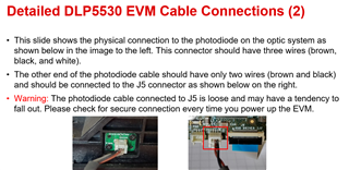
Would you be able to check the cable connections and the dmd fit as seen in this other e2e post.
I have seen issues in the pass where the DMD was not seated completely and caused some discoloration in the display.
Thanks,
Alex Chan
First, I make sure my cable connection is OK. Then we use the LED driver board of our previous dlp5530 to light up three new DLPs, two of which have a white boot screen and the other one has a yellow boot screen.
Hi Xiao Qian,
Sorry just for clarification so you have several DLP5530 EVMs available correct?
So from what I understand several of the EVMs work fine but one is exhibiting the yellow boot screen.
Did you check the DMD connection and fit as I had mentioned and linked with the previous message and e2e post?
Can you isolate the issue like lets say you have one working EVM A and then EVM B which is not working and has the yellow light. Swap the LED driver boards and see if that is an issue or see if the optics engine is the issue. Try to narrow down is it some sort of component issue.
If none of that works I may have a suggestion about flashing a new binary file onto the problem unit as there may have been an issue with calibration.
Thanks,
Alex Chan
At present, we only have the three dlp5530 EVMS newly purchased, with serial numbers of sw#3, sw#5 and sw#6 respectively. I exchanged the LED driver board and checked the working condition according to what you said, and then found that sw#5 and sw#6 can be lit with sw#3 and work normally, but sw#3 still turns on and the screen color is yellow. I checked the DMD connectivity and exchanged the LED driver board, but it still doesn't work. In addition, by exchanging the LED driver boards, the LED driver boards of sw#6 and sw#5 cannot make the three dlp5530 EVMS work normally, that is, the two driver boards may not work normally.
Hi,
Can you see if the photodiode cable is connected. This cable connector can be flimsy and can fall out easily causing issues.

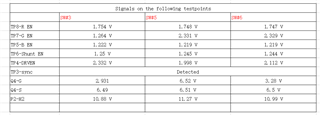
Another thing you can do is probe some of the signals on the LED Driver board. Below are some basic items to check on the driver:
Thanks,
Alex Chan
There is no problem with the connection of the photodiode, and then this is the test result of each test point of the three LED drive boards.
Hi,
I am going to need more time to look into this more but some of the values do seem concerning. Sorry for the delay and thank you for your patience.
Thanks,
Alex Chan
Hi Xiao Qian,
Sorry the instructions I had sent may have been unclear let me clarify. Can you please double check the pre regulator voltage for both setting to 6.5V or 8V you should not see a value of 10-11V like you had noted.
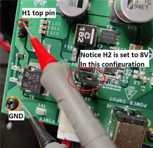
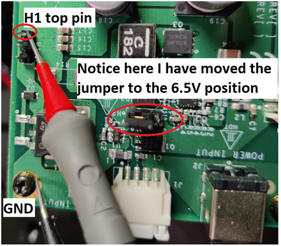
H2 there is a jumper that allows you to switch between 6.5V or 8V. You want to measure H1 with a multimeter.

See the following pictures where the red probe is touching the Pre-regulated drive voltage pin of H1 and the black probe is touching ground. In the first picture I have the jumper on H2 set to 8V so I was reading 8.08V. When I powered off the system, switched the jumper to 6.5V, I measured about 6.54V as seen in the second picture.


Please verify this as this measurement checks the voltage power rail used to power all the other components and devices with the system so if this is wrong, other things may not be powered correctly causing issues.
Thanks,
Alex Chan