This thread has been locked.

If you have a related question, please click the "Ask a related question" button in the top right corner. The newly created question will be automatically linked to this question.

DLPC4422: DLPC4422, DLPC4420, DLP660TE Bootloader destroyed

Part Number: DLPC4422
Other Parts Discussed in Thread: DLP660TE, , DLPC4420, DLPC4420AEVM

HI  Team.

Our company is producing new products using DLPC4422 and DLP660TE.

I designed th board referring to the DLPLCRDC4422VM Board.

After producing the board, I proceeded with the program as follows.

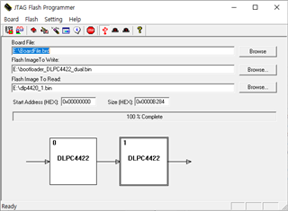
1.  install DLPC442xJTAG-1.0-windows-installer.exe


1.1 Detect Chain - UM232H  Rev 1.0
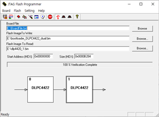
1.2 File select

    ->  Board File : BoardFile.brd

    -> Flash Image To Write : bootloader_DLPC4422_dual.bin

1.3 Program OK and Verification OK
     

2. install DLPC4422-GUI-v1.0-Setup.exe

  2.1 DLPC4422 GUI program execution.

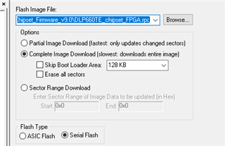
  2.2 File Selection

-> Flash Image File : DLP660TE_chipset_FPGA.rpc

 -> Flash Type : Serial Flash
 2.2 USB Reset OK

3. Program Download

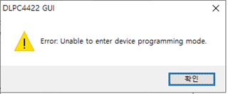
3.1 Start Download

  -> When i run Start Download, the following message is displayed.
 

4. Power On

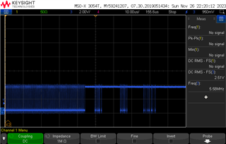
4.1 When the power on, i confirmed that data was being read from the Flash Memory.
4.1 Power Status

  -> All Power Is OK (1.8V, 2.5V, 3.3V, 1.1V etc)

4.2 Clock Status

  -> Master Clock ; 20Mhz OK

  -> Slave Clock : 20Mhz OK

  -> OCLKA : 787Khz

  -> PWRGOOD : HIGH

  -> POSENSE : HIGH

  -> MTR_ARSTZ : LOW ???

5. Questions

5.1 Is there a problems with the above process ?

5.2 In what cases does the following message appear?

   -> " Error : Unable to enter device programming mode"

5.3 Are there any other signals we should check for ?

Please help  me....

Thanks & Regards.

Kwangsam

  • Hello Kwangsam,

    Thank you for the detailed explanation of bringing up your system!

    There is a small step being skipped from what you have told me. After programming Serial Flash - FPGA file (.rpd not .rpc) - the system must be power cycled completely before continuing to program the ASIC flash.

    I have seen this error before and is related to the FPGA being busy.

    Please advise if this is no longer an issue after power resetting the system.

    Best,

    Aaron

  • Hi Aaron....

    Thanks for your reply.

    In the DLPC4422 GUI program, I first programmed the .img(Flash_Dual_DLPC4422_DLP660TE_LED.img) file into Flash memory.

    But the result is the same.

    I get the same results when programming .img files and .rpd files.

       -> 

    Which .img file or .rpd file should I program first ?

    Thanks & Regards.

    Kwangsam

  • Hello Kwangsam,

    I would advise to try programming the ASIC first with the .img file for the DLP660TE.

    A possible solution could also be to extend the Programming Mode Delay to 12000 miliseconds under Edit -> Preferences.

    Best,

    Aaron

  • Hi Aaron

    I would advise to try programming the ASIC first with the .img file for the DLP660TE

      -> I tried programming the ASIC first, but the result is the same.

    A possible solution could also be to extend the Programming Mode Delay to 12000 miliseconds under Edit -> Preferences.

      -> I set delay to 12000 miliseconds, but the result is the same.


    Ecxept RS232, is there a way to check the current status throught external GPIO or signals?

    Because i didn't connect RS232 signal.


    If possible, can you send me the new Bootloader and .Img and .rpd files?


    Are there any signal lines I need to check between the FPGA and DLP4422?

    Thanks & Regards.

    Kwangsam

  • Hi Aaron.

    Thank you for your reply.

    You send the follow reply:

    I have seen this error before and is related to the FPGA being busy.

    So I removed the Pull-down of the DLPC4422 ICTSEN Pin.

    FPFA Serial Flash Memory download has been sucessfully completed.

    However, ASIC memory download is still not possible.

    1. Are there any signals to check between the FPGA and DLPC4422?

    2. Do the .img files of DLPC4422 and DLPC4420 use the same file?

    Thanks & Regards.

    Kwangsam

  • Hello Kwangsam,

    Thank you for testing the programming of the ASIC and increasing the programming mode delay!

    To answer your questions:

    Except RS232, is there a way to check the current status through external GPIO or signals? We included RS232 signals for debug purposes. There are also indication LEDs that show the FPGA_CONF (D10).

    I could send you the bootloader, .img, and .rpd files through a private message. Please accept my request.

    Best,

    Aaron

  • Hello Aaron

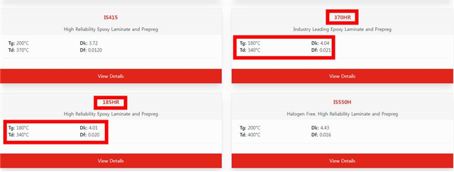
    Using ISOLA FR-370HR material, the PCB production cost is too high.

    So the company recommends ISOLA FR-185HR instead of ISOLA-370HR.

    The characteristics are as follows:

    Is it possible to use FR-185HR instead of FR-370HR?


    Current Board Status:

         1st Board : Board currently being debugged.

                         : Bootloader download -> OK

                         : DLPC4422 GUI -> USB HID class Detection OK

                         : Serial Flash, ASIC Download -> Error

         2nd Board : Production begins on January 8, 2024.


    This is the answer to your question.

    1. We know it (See DLPC442x Jtag Flash Programming document)

    We are using blue-wire mode.

    We are using J37.1 Pin connected to U22.1 Pin.

    2. We removed RS232 from the initial design as we did not think it was needed.

    1st Board : we removed R785 and R786 for debugging.

    2nd Board :  We added RS232 Port.

    3. I am programming using J41. So DNI R152 and R149 were removed.

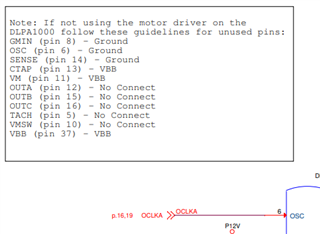
    4. We do not use motor driver. So, I set it as follows.

    1st Board : We debugged by removing R768 and R769 or tied to GND

    2nd Board : It is designed indetically to the EVM Board.

    5. 

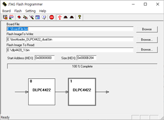
    In JTAG Flssh Programming, #0 and #1 were both successfully programmed.

    Programming -> OK

    Verification -> OK

    Board Booting -> USB Detection OK.

    Thank you.

    kwangsam

  • Hi Kwangsam,

    Aaron is out of the office for the next week and a half. Please allow me 2-3 days to find the correct person to help you out while he is out.

    Thank you very much for your patience,
    Michael Ly

  • Hello Michael.

    Before asking any questions, please provide the latest circuit diagram (DLPC4420) to produce a new board.

    We have a schematic of the DLPC4422EVM(UHD DLPC4422 Dual ASIC Formatter Board)

    We are planning to use DLPC4420 and 2 Way Actuator.

    Could you please provide the circuit diagram for the DLPC4420AEVM?

    Thank you.

    kwangsam

  • Hello Kwangsam,

    At this point, is it correct to say:

    • JTAG-BS Flash Erase/Program/Verify of boot loader for BOTH Master and Slave ASICs succeeded.
    • USB Reset command works.
    • When starting programming, you get the error "Unable to enter device programming mode".

    When programming the 442x .img file, can you confirm you are selecting:

    • "Complete Image Download" 
      • Do not select "Skip Boot Loader..." 
      • "Erase all sectors" - We can try this... not normally used.
    • Flash Type - "ASIC Flash" 
      • Do NOT select Serial Flash when programming the 442x .img file.

    Regards,
    Gary

  • Hi again Kwangsam,

    Attached is the schematic of the DLPC4420AEVM that you have requested.

    Regards,
    Michael Ly

    DLP072H_SCH.pdf