This thread has been locked.

If you have a related question, please click the "Ask a related question" button in the top right corner. The newly created question will be automatically linked to this question.

DLPC3430: DSI signal sent but no video(only rectangle?grid pattern)

Part Number: DLPC3430
Other Parts Discussed in Thread: DLPC3435, DLPC3438, DLPC3433, DLPC3432, USB2ANY

Hi,

I'm trying to send the video signal to our custom board with DLPC3430. However, there is nothing change with the image.

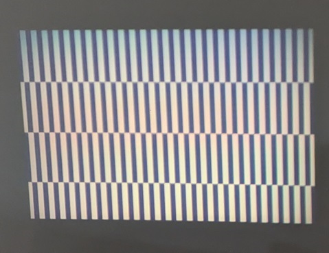
It remains the original pattern from the external video port setting.

Here's current setting and reference documents

1. Reference:

  • DLPC3430, DLPC3432, DLPC3433, DLPC3435 and DLPC3438 Software Programmer's Guide(dlpu020e.pdf)
  • DSI Setup and Debugging Guide v1.0
  • DLPC3430 and DLPC3435 Display Controller(dlpc3430.pdf)
  • DSI-HSClock.xlsx(download from TI forum)

2. Board status:

  • dlpc3430 IC init complete(host_irq goes low and LEDs are on)
  • i2c interface works and it can read/write commands correctly
  • show grid pattern only
  • instrument measure: no LP mode on clock lane (no 1.1V signal)
  • instrument measure: data lane looks like DSI Setup and Debugging Guide v1.0 figure. 4

3. DSI settings:

  • 2 data lanes 
  • Video mode (Burst)
  • RGB565 16bits
  • EOT enabled
  • BTA disable
  • Horizontal Front Porch: HS Mode
  • Horizontal Back Porch: HS Mode
  • Vertical Active: HS Mode
  • Vertical Front Porch: LP Mode
  • Vertical Back Porch: LP Mode
  • Vertical Sync Time: LP Mode 
  • Clock lane is always provided

4. DSI parameters and clocks

  • HS clock: 135MHz
  • Input resolution: 848x480
  • Video frame rate: 60
  • Pixel format: RGB565
  • Hsync Pulse Width: 110 PCLK
  • Hori Back Porch: 110 PCLK
  • Hori Front Porch: 16 PCLK
  • Vsync Pulse Width: 8 Lines
  • Vert. Back Porch: 23 Lines
  • Vert Front Porch: 6 Lines
  • PClk: 33.6257 MHz (set 34MHz)
  • DSI HS Clock: 134.5 MHz (set 135MHz)
  • HSPrepare: 76
  • HSZero: 400
  • HSExit: 100
  • HSTrail: 120
  • Clk Prepare: 38
  • ClkZero: 262
  • ClkTrail: 60
  • ClkPre: 60
  • ClkPost: 447

5. dlpc3430 settings (write thru i2c and read back for confirmation)

  • Read Display Size (13h): 854x480
  • Read Input Image Size (2Fh): 848x480
  • Read Image Crop (11h): 848x480
  • Read DSI Port Enable (D8h): 0
  • Read Input Source Select (06h): 0
  • Read External Video Source Format Select (08h): 0x21
  • Read Short Status (D0h) 0x10000001
  • Read System Status (D1h): 0x0 0x7 0x0 0x0

Do I miss something? and here are some additional questions

  1. During HS video Mode, commands are sent in HS or LP mode?
  2. If some parameters or clocks set error. Should I get a distorted image or no image(grid pattern only)? 
  3. Is there any way to figure out the dlpc3430 receive the DSI data or not? (even the data in error format)  

Thank you.

T.H.

  • Hello T.H.

    Welcome to DLP forum and thank you for your interest in DLP technology.

    I understand that the board is booting and is able to display image  from internal test pattern. However, the content video sent over DSI interface is not displaying and output image remain to be previous internal test pattern. Please use the latest version of firmware.

    We have uploaded a diagnostic tool which allow you to read the status and also allow for various evaluation. Please download the tool from following link and 

    "DLP-PICO-HARDWARE-DIAGNOSTIC-TOOL  DLP Pico Hardware Diagnostic Tool" from the product folder page

    DLPC3430 data sheet, product information and support | TI.com

    Please use this tool diagnose the issue and report back your findings.

    While experimenting, please also try following changes if possible:

    1. Try changing input resolution to 854 x 480 from  848 x 480. Please refer to release note of firmware, there may be issue in with lower resolution incase of DSI.

    Release Notes (ti.com)

    2. Please change pixel format to RGB (24 bit) from RGB5656

    I have uploaded a latest version of the DSI parameter calculation worksheet and please use this sheet to share your configuration.

    DLPC34XX-DSI-HSClock.xlsx

    Plese let us know your findings after this experiments.

    regards,

    Vivek

  • Hi Vivek,

    Thanks for your support. For the diagnostic tool firmware, I can not update it into the flash immediately due to some technical restriction.

    The firmware for dlpc3430 on the board now is version 7.4.2. By your suggestions, I have a quick try with following settings.(check the excel fire) 

    3527.DLPC34XX-DSI-HSClock.xlsx

    The device still shows the init grid image. 

    I also check the release note and i2c settings. The single buffer mode and idle mode are NOT enabled.

    Here are some questions:

    1. For the diagnostic tool part, if the device can change test pattern(grid/color bars) correctly by i2c commands. Does it mean "boot successful"?
    2. If I send DSI signals with clock error or timing error, there will be distorted images or just NO image(default pattern only)?

    Thanks.

    T.H.

  • Hello TH,

    1. Are you changing the image seen via test pattern generator? If you are changing the image on the wall and you are communicating successfully with the DLPC then the system as booted.

    2. This really depends, what are you seeing now? Please use the Hardware Diagnostic tool to run the Diagnose DSI Setup Problems and then Diagnose DSI Runtime Problems. These should make sure each setting is properly configured and allow you to easily tweak them while running. Providing screenshots of the printouts and photos of your image on the wall may also help us in debugging.

    Best,

    Maximus

  • Hi Maximus,

    1. Yes, I use i2c commands to change test pattern with test pattern generator(checkerboard, color bars...).

    2. The default pattern of "external video source" (picture below). I will check the diagnostic  tool asap, it looks like requires some usb-i2c dongles...

    Question:

    1. Should I keep all DSI lanes in LP11 (1.1~1.2V) before dlpc3430 init complete?  "All lanes" means clkp/n, data0p/n,
      and data1p/n (for DSI two lanes setting) 

    Regards,

    T.H.


  • Hello T.H.,

    You are correct, you should be in  LP11 mode before the controller initializes. Correct startup sequence:

    1. Initialize DSI controller in SOC to operate in LP11 mode
    2. Drive proj_on to projector, wait for host irq to go low
    3. Perform I2C configuration of projector (DSI clock speed is configured first)
    4. Transition DSI controller to HS mode

    The image you posted is something we've seen before. Typically this is projected when you are in external video source mode but there is no video/image being driven. Can you confirm you are driving a video/image source?

    The Hardware Diagnostic tool can be connected to the board the same way you would for the DLP GUI. This can also tell you if you are having DSI source issues.

    Best,
    Maximus

  • Hi Maximus,

    Thanks for your support. 

    I have put the same code on our MCU's(which is the DSI front end) evaluation board. The panel on the EVB works good.

    There should be some "correct" DSI signals ...I think.

    I will take a further look at the DSI lanes part. Also, Hardware Diagnostic tool will be involved later.

    By the way, the USB2ANY noted in Hardware Diagnostic tool document

    Regards,

    T.H.

  • Hi T.H.,

    Yes that is the USB2ANY device. 

    I am looking at your timings and you may need a slightly higher DSI HS clock, I have attached a DSI timings calculator below. Also did you make sure to write the DSI HS Clock rate to the DLPC? This is opcode (BDh) from the DLPC3430 Software Programmer's Guide.

    Best,

    Maximus

    1881.DSI-HSClock.xlsx

  • Hi Maximus,

    Yes, I set the HS Clock via i2c after dlpc3430 init complete. I will make a further update after I get the usb2any device.

    By the way,  I have tried the settings with your excel file but it is still nothing.

    Thanks

    T.H.

  • Hi T.H.,

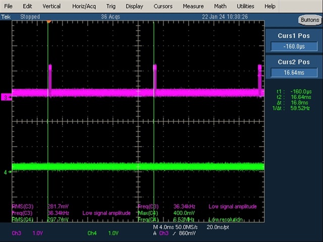
    It may be worth getting some oscope images to verify the proper initialization of the DSI lanes and that data is being setup. How is your DSI signal setup/being sent?

    Best,

    Maximus

  • Hi Maximus,

    Here's my DSI and DLPC power/setting sequence. all power on or gpio action are triggered by MCU's GPIOs, except MCU power.

    1. MCU power on
    2. Start DSIHOST in MCU
    3. Delay 100ms (measuse 6 dsi lanes are at around 1.1volt)
    4. SYSPWN ON  then PROJ_ON
    5. wait for HOST_IRQ goes low
    6. set parameters thru i2c and read back for confirmation
    7. start sending DSI signals from DSIHOST

    The pink line is the data lane(60fps) and the green line is the clock lane(around 200mv)

    Thanks.

    T.H.

  • Hi T.H.,

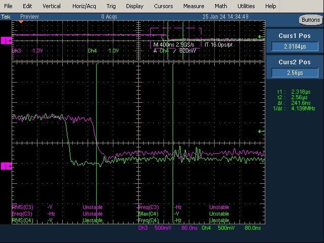
    Thanks for this could you also provide a scope shot of HOST_IRQ, CLK positive/negative, data positive/negative during startup? This will help us verify the lines are going through the proper startup sequence.

    Best,

    Maximus

  • Hi Maximus,

    It is not available to probe the host_irq pin on our custom board now. By the way, I found the MCU sets the "tHS-PREPARE+tHS-ZERO" at around 240ns, which is not in compliance with the dlpc3430 document's regulations. I will check this with the MCU provider and make a quick reply later. 

    Thanks

    T.H.

  • Hi T.H.,

    It is important to make sure the DSI host is sending video following the appropriate timings the DLPC is configured for, please update us if this does not resolve the issue. 

    Best,

    Maximus

  • Hi Maximus,

    After increasing the "tHS-PREPARE+tHS-ZERO" time by adjusting the target FPS. The DSI signals can be correctly projected now.

    Thanks for your support. This is the final setting.

    DSI-HSClock_24Bit_30FPS.xlsx

    Thanks,

    T.H.