Other Parts Discussed in Thread: DLPLCRC900DEVM
Tool/software:
Hello,
please help,
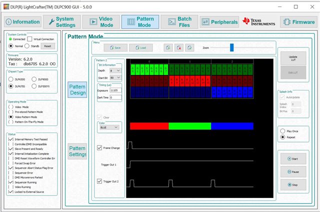
I lost vide-pattern-mode. It simply stops to work next day.
Some times I have nothing on the DMD, sometimes first image of sequence, sometimes only half of dmd change the state.
We tried with other PC, there is a strange pattern on the dmd something like a lightning in the sky.
Pattern mode is ok, video mode is ok.
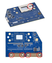
Tight "the dlp screw" doesn't help.
Thank you