


Other Parts Discussed in Thread: DLP7000UV
Tool/software:
Hi,
I am bringing up a custom board with a Kintex UltraScale+ and DLPC410 and I am having issues getting anything displayed on the DMD.
Since the two FPGAs have different voltage levels, we use the following procedure on the startup:
- KU+ gets configured first from an on-board Flash
- After it has checked that all power supplies are OK, it releases PROGB on Virtex-5 (DLPC410), letting the Virtex-5 configure itself from the Flash (DLPR410)
- KU+ then turns on a 50 MHz clock into the CLKIN pin on DLPC410
- After that KU+ turns on all LVDS drivers, driving the prescribed init pattern
- And after that, KU+ starts a FSM that first asserts reset on DLPC410 (ARSTN pin) and waits for INIT_ACTIVE to go low, and waits for another 64 clock cycles
The DLPC410 reports the correct DMD type (1, for DLP7000UV) and DDC version (0, for DLPR410BYVA).
When I try loading the image into the DMD nothing happens. Eventually (a couple of seconds later, consistent with the 10 second timeout) the watchdog kicks in and the mirrors go into a random position, and if I drive PWR_FLOAT high I can see mirrors "clear".
The procedure that I use to load the DMD image is basically the same as the one used in APPSFPGA for global reset: in the first row the address is set to 0, and it gets incremented in the subsequent rows, and when all rows were transferred a global reset is issued, and VALID with NO-OP is clocked for another 100 cycles.
I have noticed that the initialization procedure takes roughly 13 ms (in contrast to the 220 ms mentioned in the datasheet). There is a forum post (https://e2e.ti.com/support/dlp-products-group/dlp/f/dlp-products-forum/760900/ccs-dlpc410-rst_active-is-not-asserted-regularly) that suggest a poor signal integrity might be a cause for incorrect initialization.
Since we have a JTAG header connected to DLPC410/Virtex-5 I have decided to develop small design for Virtex-5 to validate the signal integrity on the LVDS lanes (using IODELAY and ISERDES_NODELAY, MicroBlaze scans the IODELAY tap value and reports the alignment it measures on the output of ISERDES). Everything looks great there, the data valid window is roughly 1.25 ns, consistent with 400 MHz DDR data rate. Example for a couple of lanes:
V5> scan all
        |           1         2         3         4         5         6
tap pos | 0123456789012345678901234567890123456789012345678901234567890123  1st  2nd len
--------|-------------------------------------------------------------------------------
A ch  0 | 1111111111xx444444444444444x333333333333333xx222222222222222x111  (12, 27, 15)
A ch  1 | 111111111x444444444444444x3333333333333333x222222222222222x11111  (10, 25, 15)
A ch  2 | 1111111111x444444444444444xx333333333333333x222222222222222xx111  (11, 26, 15)
A ch  3 | 111111111x44444444444444443333333333333333xx222222222222222x1111  (10, 26, 16)
A ch  4 | 1111111111xx444444444444444x3333333333333333x2222222222222222x11  (12, 27, 15)
<...>
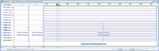
NS_FLIP, COMP_DATA and RST2BLKZ are kept low (see the screenshot below) as mentioned in the datasheet.
What else could cause the initialization procedure to not complete properly? What should I check to figure out why it only takes 13 ms instead of 220 ms?
Thanks,
Jan

