This thread has been locked.

If you have a related question, please click the "Ask a related question" button in the top right corner. The newly created question will be automatically linked to this question.

DLP4710EVM-LC: EVM only displays half of the pattern in every mode

Part Number: DLP4710EVM-LC
Other Parts Discussed in Thread: DLPC3479

Tool/software:

Hello,

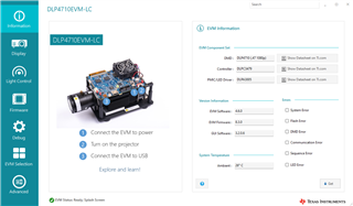
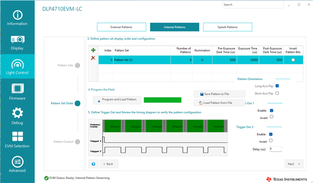
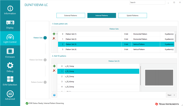
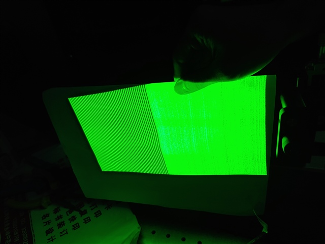
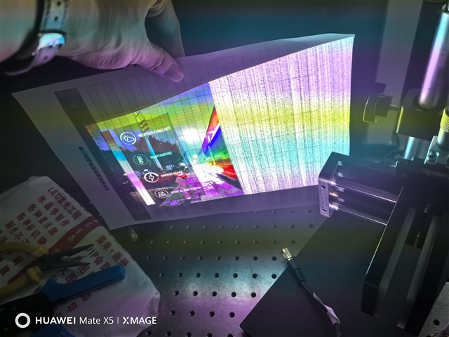
The DLP4710EVM-LC have problem that it only displays half of the image in every mode. The issue occurs in "light control" mode , "display" mode .

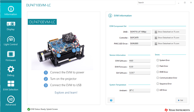
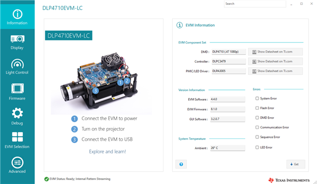
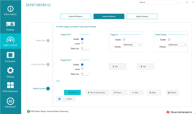
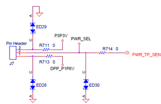
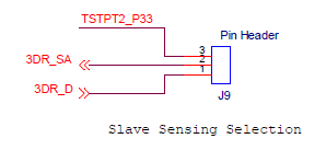
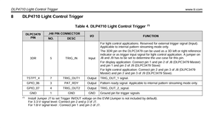
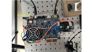
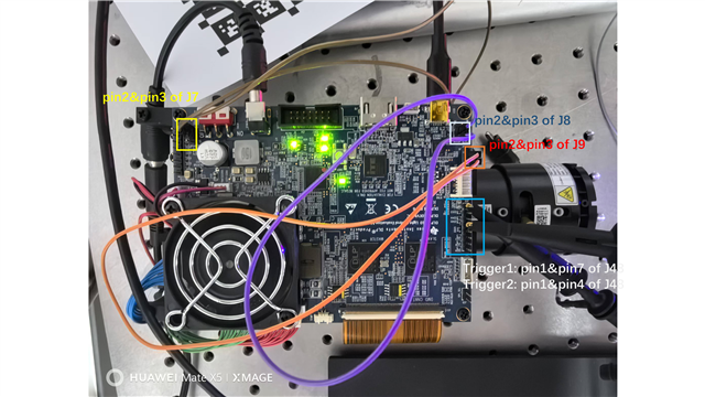
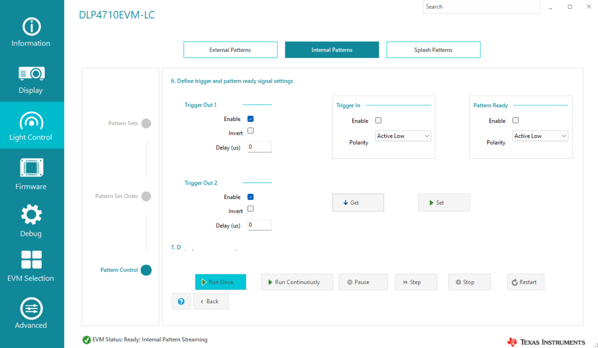
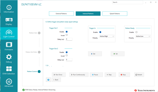
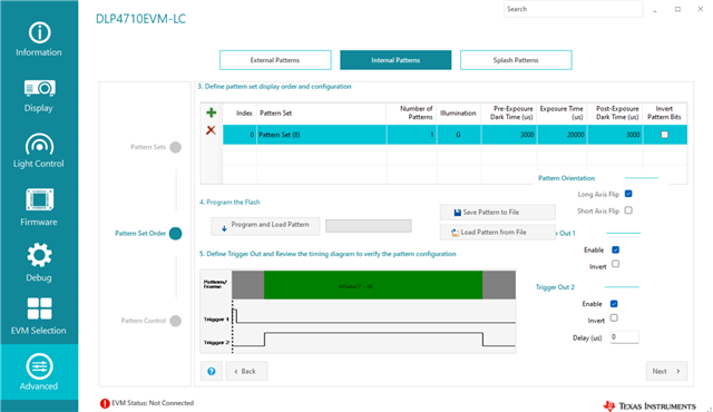
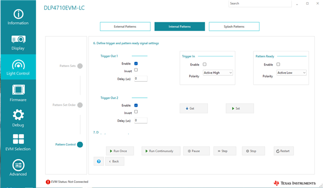
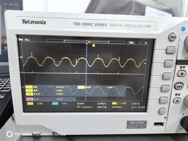
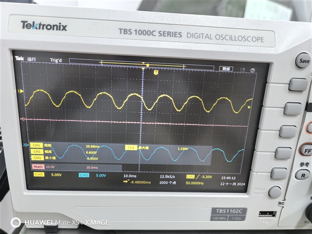
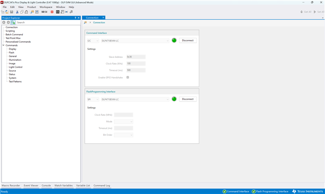
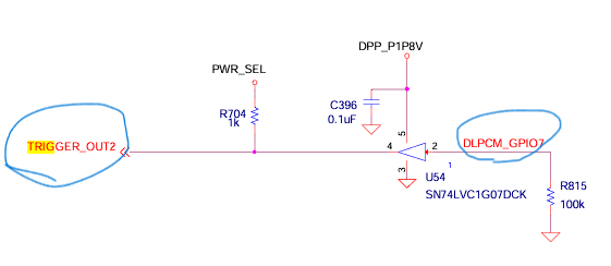
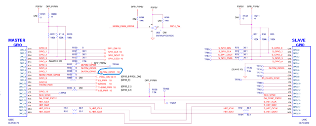
At first , the EVM can normally display patterns , but it cannot output "triiger2" signal in light control mode and it can output "trigger1" signal (I have connected pin2 and pin3 of J7 , pin2 and pin3 of J9). So ,I update the firmware and the EVM cannot display pattern normally. I have updated firmware in version "v8.1.0","v8.3.0" and "v8.4.0" , but the issue still occurs and the EVM also cannot output trigger signal.

Looking forward to your reply!

Best,

Zhiyuan Liu

  • Hello Zhiyuan,

    I'm sorry you are having issues with the EVM. How long have you had the module for and which version of the software is currently on the EVM?

    I'd recommend reading back on the Information page of the GUI and share a screen capture of the page.

    Also, please advise if both LEDs D33 (M_HOST_IRQ) and D32 (S_HOST_IRQ) are on?

    Best,

    Aaron

  • Hello Aaron,

    We bought the EVM about 6 months . We bought the EVM in 24th April . However , we didn't used the EVM from july to 4th November , and the issue occurs in 4th November. 

    I have updated firmware of 3 different versions , and the informations of 3 versions are showwed above . The issue still occurs in these firmwares. I notice that the D33(M_IRQ) and the D34(S_IRQ) both light up when I turn on the EVM . 

    Best,

    Zhiyuan Liu

  • Hello Zhiyuan,

    I notice you are trying to run on software 3.2.0.6, could you please try and run on 3.2.0.7 available on ti.com?

    This is under the DLPC3479 - here.

    Best,

    Aaron

  • Hello Aaron,

    I uninstall the GUI 3.2.0.6 and install the GUI 3.2.0.7 . Also , I updated the firmware including v8.1.0 , v8.3.0 and v8.4.0. Here is the screenshot of the information page of GUI.

    The issue still occurs. I also test the output trigger .The output trigger1 signal is normal , but the output trigger2 signal can not be detected.

    Best,

    Zhiyuan Liu

  • Hello Zhiyuan Liu,

    Please share a screen-grab of the Internal Pattern or External Pattern screen you have defined when you are trying to display your image, the Trigger Out 2 setting should be 'Enabled' if you want to view this.

    Could you also go to the advanced mode and perform a 'Get' for the 'Display' tab input 'Input Image Size', 'Image Crop', and 'Display Size' fields?

    Best,

    Aaron

  • Hello Aaron,

    The firmware version is v8.4.0 and GUI version is v3.2.0.7 . The screenshot of "internal pattern" in light control mode are showwed as below. As you see , I set "enable" of trigger1 signal and triiger signal , and trigger1 signal can be detected while trigger2 signal cannot be detected. The trigger1 signal and trigger2 signal both be set "enable" in last few days' detection , and the issues always occur.

    The screenshots of advanced mode are showwed as below. I didn't change any settings in advanced mode. The issues seem like one of controller lose control of half DMD and it fail to output trigger2 signal. I wonder if the EVM has some hardware damage? If the EVM has some hardware damage , where can I find maintenance service?


    best,

    Zhiyuan Liu

  • Hello Zhiyuan,

    I agree that there is something wrong here. I need to refer back to the original question here where you stated:

    "

    I have connected pin2 and pin3 of J7 , pin2 and pin3 of J9

    "

    Are these the connectors you are referring to?

    Could you please advise further on how you are connecting these? Are you connecting Pin2 to Pin2 / Pin3 to Pin3? Or are you shorting Pin2-Pin3 on both or something different?

    Lastly, where are you testing Trigger 1 and Trigger 2 as well as Trigger In?

    Best,

    Aaron

  • Hello Aaron,

    Are these the connectors you are referring to?

    These connectors are I referring to. I have connected pin2-pin3 directly both. I use a oscillograph detecting pin1 and pin4 of J48 to get trigger2 signal and detecting pin1 and pin7 of J48 to get trigger1 signal. As you see , I get the information from the user guide of DLP4710EVM-LC 

    best,

    Zhiyuan Liu

  • Hello Zhiyuan,

    Thank you for specifying that and sharing exactly what you were referring to, many issues are resolved on E2E with clarifications like this.

    This has also highlighted what is wrong here, for display or light control applications using the Trigger In function the secondary controller also needs to be set through J8 connection. It should be as below:

    Application J7 (In/Out 3.3V) J8 (Primary) J9 (Secondary)
    Display 2-3 1-2 1-2
    Light Control 2-3 2-3 2-3

    Please advise if you are still getting a half-image after connecting J8 as well.

    Best,

    Aaron

  • Hello Aaron,

    I have connected pin2 and pin3 of J8 , but the issue still occurs. 

    best ,

    Zhiyuan Liu

  • Hello Zhiyuan,

    I'd like to make sure you have J48 connection correct, you have labeled pin 7 and pin 4 being tested for Trigger 1/2 and you have connected pin 1 and 4:

    This would be GND (pin1) and Trigger_Out2:

    previously you also shared that you have no trigger_in enabled in your internal pattern project please enable this if you are intending this:

    Lastly, to test which controller is having an issue, we can use the advanced mode -> Projector Control -> Debug -> Write ASIC Select and utilize ONLY the Master or Slave controller and see which controller is not responding to a display update or change through TPGs.

    Please start testing this and let me know what you find. When did you purchase your EVM?

    Best,

    Aaron

  • Hello Aaron,

    1,

    I set "trigger in" to "Enable". We don't have a 3.3V square wave generator , so , I use a 3.3V DC power supply connect its negtive electrode and pin1 of J48. When I use its positive electrode touch the pin5 of J48, the projector's "light control" function can be activated but the issue still occurs. Here is the settings .

    2,

    I do have tested "trigger out 1" signal using a oscillograph and connect pin1 and pin7 of J48 . Also , I do have tested "trigger out 2" signal using a oscillograph and connect pin1 and pin4 of J48 . Here is the light control settings.

    Here is the photos of the oscillograph. As you see, in photo1 , the yellow line means the voltage of pin7 while the blue line means the voltage of pin1 . And the red line means the voltage of pin7 - pin1 . So, the trigger1 signal is  normal . However , in photo2 , the  the yellow line means the voltage of pin4 while the blue line means the voltage of pin1 . And the red line means the voltage of pin4 - pin1 . The trigger2 siganl cannot be detected.

    photo1

    photo2

    3,

    Lastly, to test which controller is having an issue, we can use the advanced mode -> Projector Control -> Debug -> Write ASIC Select and utilize ONLY the Master or Slave controller and see which controller is not responding to a display update or change through TPGs.

    I can't find a mode named " Projector Control" in advanced mode.

    I wonder if there's something wrong with the master controller? According to the DLP4710EVM-LC schematic file, the trigger2 signal comes from the master controller.

    4,

    We purchased the EVM on Mouser on April 24, 2024. Where can I find repair service if the EVM has some hardware damage? Can you recommend some repair services in China?

    best

    Liu Zhiyuan

  • Hello Zhiyuan,

    I'd like to reach out to you directly and we could see if we can replace this.

    Please accept my connection.

    Best,

    Aaron