This thread has been locked.

If you have a related question, please click the "Ask a related question" button in the top right corner. The newly created question will be automatically linked to this question.

DLPA2000: DLAP2000 buck-boost regulator

Part Number: DLPA2000
Other Parts Discussed in Thread: DLPC3430

Tool/software:

Hello,

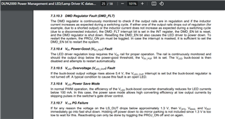
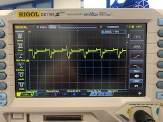
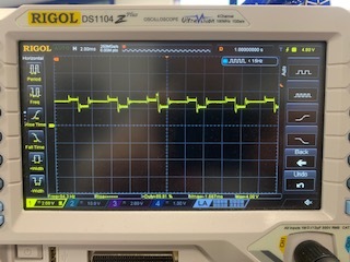
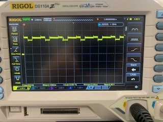
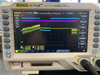
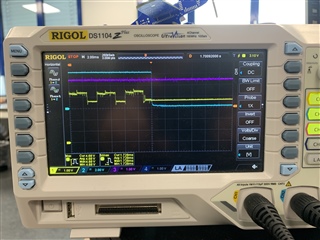
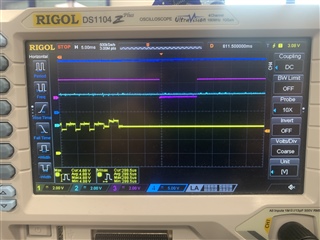
We have implemented a system using the DLP3430 and DLPA2000. However, we’re encountering an issue when setting the display brightness to maximum. When this happens, the display freezes and turns black and white. We performed some measurements, and the waveform on the VLED pin is as shown in the attached image. Additionally, when this occurs, the V6V signal drops to 0 volts for a brief period.

Could someone provide assistanc 
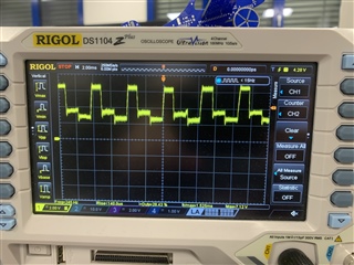
e with this issue? Thank you in advance!

  • Hello User,

    Welcome to the E2E forums and thank you for your interest in DLP ® technology. 

    I just want to double check that this is a custom system you have designed and not the DLPDLCR2010EVM? If it is a custom design were you basing it off of this reference design? (https://www.ti.com/tool/TIDA-00325)

    The voltage measurements you have taken seem to be outside of the normal operating conditions of the DLPA2000 for VLED. The below specifications are from the DLPA2000 datasheet. Additionally what LEDs are you using with your design? 

    I see from the DLPA2000 datasheet here that there are these fault conditions descriptions that perhaps may be what is occuring.

    What do the waveforms look like at a lower brightness for VLED?

    Regards,

    Alex Chan

  • Hello User,

    How do you change the display brightness to maximum (from what value to what value)? Do you change the RGB LED current to achieve the display brightness?

    Can you still have communicate with the DLPC3430 when the display freezes? 

    Regards,

    Lori 

  • Hello, thank you for your response.

    Yes, it is a custom design.

    I’ve checked the datasheet, and based on the measurements I sent for VLED, I agree that the voltage was too high. I managed to stabilize it by increasing the capacitance on VINL of the DLPA2000. Previously, it was 150µF, and now it’s 440µF (2x220µF). On the VLED pin, we currently have a 47µF capacitor (which we haven’t changed).

    With this adjustment, the voltage level has stabilized so far, as shown in the attached pictures. However, the problem persists when I try to exceed 90% of the display brightness.

    Do you think increasing the 47µF capacitor on VLED would help in this case?

    VLed at minimun brightnees.

    VLed at 50% of the brightnees.

    VLed at 90% of the brightnees.

  • Hello User,

    Please give our team some time to look into this issue we will need to check with the hardware team.

    Was your custom design previously reviewed by anyone from TI?

    Regards,

    Alex Chan

  • Hello, 

    No it was not reviewed. Also can you confirm the wave form I should have in Vled pin. 

  • Hello user,

    Thanks. Our team will need to look into this and get back to you by the mid of next week.

    Regards,

    Lori 

  • Hello Alvaro,

    I don't immediately see anything wrong with your Vled waveform. Could you please check the status of each of these power lines before and after the fault occurs?

    Additionally can you please confirm the firmware you are using?

    Best,

    Max

  • Hello Maximus,

    I have reviewed the power lines from Figure 5 and observed that the V6V line drops when the Buck-Boost regulator stops working. As shown in the following pictures, the rest of the signals do not appear to be affected.

    Channel 1: VLED

    Channel 2: V6V

    Channel 3: LS_OUT

    Same Pic (Zoom in)


  • Hello,

    Thank you for this information, could you please send me your PMIC schematic? I am discussing this issue internally with our hardware team to see if they have seen this issue before.

    Best,

    Max

  • Hello,

    This is the schematics or the PMIC, also this the firmware version I got:

    System software version:
    Register: 0xD2
    Value: 0x01

    Flash Build Version:
    Register: 0xD9
    Value: 0x0B

    C106 and C107 are not populated.

  • Hi Alvaro,

    Thanks for the quick response, is your Vin 5V here or something else?

    Best,

    Max

  • Hello Alvaro,

    More specifically could you check the system power input for glitches or sags as well as check if RESETZ or INTZ go low?

    Best,

    Max

  • Hello,

    Between 3.7V and 4.2V.

  • Hello,

    Ch1: VLED

    Ch2: Vin

    Ch3 RESETZ

    Ch4: INTZ 

  • Hi Alvaro,

    Thank you for this, let me get back to you once I have evaluated it with our hardware team.

    Best,

    Max

  • Hi Alvaro,

    Could you please confirm the following:

    • How many systems are you having the issue on, is it just one or all?
    • Do the LEDs still function after you experience this behavior? 
    • Why is your input voltage varying so much? I believe you mentioned this was 3.7-4.2V 
      • How are you powering your board?
    • Where did you get your firmware from? Was it the TI DLP Pico Firmware Selector tool or else where and what was the .img file named?
    • Can you share your LEDs or LED spec and how they are connected to your board? 
    • Is your proj_on signal stable while you experience this behavior?
    • Are you using 100 milli ohms as your Rlim sense resistor? Our reference designs use 39 milli ohms and thus our default firmware is configured for 39 millohms as well.

    Best,

    Max

  • Hello Maximun,

    • How many systems are you having the issue on, is it just one or all?

                In all of them.

    • Do the LEDs still function after you experience this behavior?

                Yes, they still work but the mage gets frozen.

    • Why is your input voltage varying so much? I believe you mentioned this was 3.7-4.2V 
      • How are you powering your board?

               Because, the boar is powered by a battery. We experiment this proble even when the battery is fully charged. 

    • Where did you get your firmware from? Was it the TI DLP Pico Firmware Selector tool or else where and what was the .img file named?

           The firmware we got from the light enginee vendor.     

    • Can you share your LEDs or LED spec and how they are connected to your board? 
    • Is your proj_on signal stable while you experience this behavior?

            Yes, proj_on is stable.

    • Are you using 100 milli ohms as your Rlim sense resistor? Our reference designs use 39 milli ohms and thus our default firmware is configured for 39 millohms as well.

           We are using 100 milli ohm.

  • Hi Alvaro,

    Thank you for sharing this information. What optical engine supplier are you using? I would recommend reaching out to them to provide you with a new firmware build with the Rlim set to 100 milli ohms and double check the UVLO settings and transient current limit. Additionally I would recommend you increases your time scale while monitoring your Vin on the oscilloscope to check there are no spikes or dips which could trigger the UVLO or some other fault.

    Best,

    Max

  • Hello Max,

    Thank you for your time and support. The issue was resolved by adjusting RLIM for our setup. We found that a range of 0.15 < RLIM < 0.3 works effectively.

    If you have any further suggestions regarding this change, I would appreciate your input.

    Thank you in advance for your assistance.

    Best,

    Alvaro

  • Hi Alvaro,

    Glad we could narrow down the issue, feel free to reach out if you have any other issues!

    Best,

    Max