This thread has been locked.

If you have a related question, please click the "Ask a related question" button in the top right corner. The newly created question will be automatically linked to this question.

DLPC4420AEVM: DLPC4420AEVM+DLP780TE USB device appears for a few seconds and allows me to communicate with the DMD via the DLPC44xx GUI

Part Number: DLPC4420AEVM
Other Parts Discussed in Thread: DLPC4420, DLP780TE, DLPA300,

Tool/software:

DLPC4420AEVM: USB device disappear after a few seconds - DLP products forum - DLP®︎ products - TI E2E support forums

hello,  I followed the user manual instructions to set up the system, but I am encountering a critical issue during operation. and  I am encountering the same question 。How solution at the fina?(TheDLPC4420AEVM board is  purchased not long ago.i used this board first time.

Issue Description:

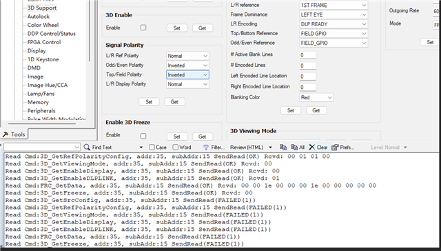
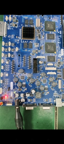
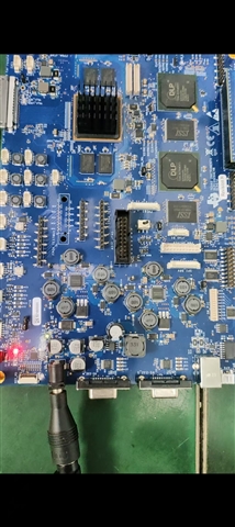
  • When I power on the DLPC4420EVM, the USB device appears for a few seconds and allows me to communicate with the DMD via the DLPC44xx GUI.
  • However, after a few seconds, the screen goes black, the USB device disappears from Windows Device Manager, and I lose all control over the DMD.
  • During the short period when USB is active, I am able to load test patterns and make adjustments, but as soon as the USB disconnects, the DMD stops displaying any content.
  • The issue persists even when using different power supplies and USB cables.
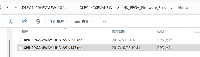
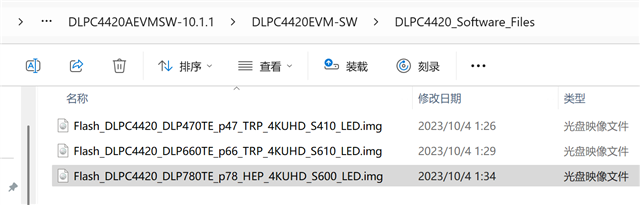
  • I have already reflashed the firmware multiple times using Flash_DLPC4420_DLP780TE_xxx.img, but the issue remains the same.
  • Hello,

    It seems like you've seen the same issue as the attached E2E thread, right?

    Can you please measure the DMD power up sequence and the DLPA300 power up/down sequence and share the captures in the thread here? Please refer to the measurements on the attached E2E.

    Regards,

    Lori 

  • Thank you for your response.

    Below are the results:

    VDD1 :remain at 1.8V,BOTH SW1 ON and OFF。

    VCC2:At 0V before SW1 OFF,remain at 10V after SW1 ON.

    VOFST:at 0V before SW1 is turned on,remain at 11.3V after both SW1 is turned on and the logo disappears.

    VBIAS:at 0V before SW1 is turned on,remain at 20V both SW1 is turned on and the logo disappears.

    SCPEN and IRQ remain at 3.3V both before and after SW1 is turned on.

    RESET is at 0V before SW1 is turned on, then stays at 3.3V until the logo disappears.

  • Hello,

    Do you mean when the logo disappear, VOFFSET and VBIAS are remaining at 11.3V and 20V accordingly?

    Can you please share the waveform capture? I also would like to see the power up sequence/timing. 

    Regards,

    Lori 

  • Yes,when the logo disappear,VOFFSET and VBIAS are remaining   at  11.3V and 20V.the waveform as follows picture 2。( the power up sequence as Figure 1
     

    What problem of this board?

    Thank you for you help

    Best Regards

  • Hello,

    Can you please provide the power sequence as section 8.2.3 on the DLPA300 datasheet? 

    For example, capture 1 (CH1: VOFST; CH2: VBIAS; CH3: DMD_RSTZ; CH4: VRESET). Capture 2 (CH1: VOFST; CH2: P1P8V; CH3:DMD_RSTZ; CH4: VCC2).

    Meanwhile, can you please confirm you have followed the quick start procedure in the DLPC4420AEVM user's guide? Do you see any change if you re-program the EVM?

    Regards,

    Lori  

  • I only have two channel probes now.Figures 1 and 2 show the High Voltage Power-Up Sequence.And i don‘t  see any change after re-program the EVM.

  • Hello,

    Based on your captures, I have a few questions:

    1.You've never seen VRESET boot up, right? This doesn't make sense if you see the image on the DMD after power up.

    2. The captures that you shared above are the whole process when you see the image on the DMD, then the the image disappear and you cannot communicate with GUI? 

    I suspect that you should see a voltage drop when the image disappear. 

    3. It seems like the same behavior can be repeatable, right? That means, every time you power cycle the EVM, you can see the image on the DMD, and after a few seconds, the image disappear and you can't communicate with GUI. 

    Regards,

    Lori 

  • Hello

     1.Yes, I never seen VRESET boot up.

     2. After powe on, the USB is connected and a logo appears. After the logo disappears, the USB is not connected.

     3.Every time i power on cycle the EVM, this behavior can be repeatable.

     4.The captures that I shared above are the whole process when you see the image on the DMD, then the the image disappear and you cannot communicate with GUI.And i don't see a voltage drop when the image disappear.(Just appeared voltage drop untill SW1 is turned off)

    What problem of this board?How to solve it ?

  • Hello,

    Thank you for the information. 

    Can you please provide UART log in text file?

    To get UART debug, you will need:

    1. An RS232-to-USB cable to connect to your PC. This is how we read back debug logs on many of our EVMs.

    2. The debug log is sent through serial port using a baud of 115200. I would recommend using the TeraTerm application but many are available.

    Meanwhile, can you please check the LEDs on the DLPC4420AEVM and provide the status of the LEDs?

    Regards,

    Lori 

  • Hello

    [09:08:10.930]received←◆In Bootloader: v10.0
    
    Debug opened on URT0
    \0Fetching data from EEPROM device 3280 bytes
    
    [09:08:11.186]received←◆eeprom: EEPROM content is valid
    EEPROM: Initializing Slave EEPROM: 3280 bytes
    
    [09:08:11.442]received←◆sysmon: System Startup State From AppCfg is 0
    sysmon: Notify uC ASIC is running.
    sysmon: 1.8V power enabled via PMD
    
    [09:08:11.504]received←◆
    Serial Flash NVM = 0xEFCF
    
    sysmon: Low-power mode change cc = 1
    sysmon: Memory test cc = 1
    sysmon: System mailbox ID = f7ff6670
    API version: 0a.01.01
    App version: 0a.01.01
    ASIC ID: 50
    ASIC Configuration: 4422
    Configuration layout versions:
    Seq Map: 44.21.0021
    SW Map: 44.21.0000
    EEPROM: 10.01.0001
    DMD_Init - Complete
    *****Through DDP_Init cw & seq*****
    projectorCtl: Opening projector control on USB
    [09:08:11.603]Regards←◆
    
    illumination: Starting SSI Initialization...
    Configuring PWM Driver...
    PWM Driver initialized...
    Setting PWM Drive Levels to 0...
    Configuring Sensor. Type = 1.
    Initializing CCI configuration...
    SSI_Calibration EE_GetVAR command Successful...
    SSI initialization complete
    illumination: DDP_ILLUMINATION_TYPE_SSI illum_Init Completed
    sysmon: Through _sysReset
    sysmon: System Startup State From AppCfg is 0
    sysEvent: SYSEVENT_START
    sysmon: MASTER ASIC
    Sysmon: Transitioning to normal run mode
    systemmode: There are 4 defined System Modes
    datapathf: StopCurrentOperation complete
    systemmode: TwoD System Mode Table Created
    
    datapathf: Transition to SUSPENDED
    systemmode: HighSpeed System Mode Table Created
    systemmode: XPR System Mode Table Created
    systemmode: ThreeD System Mode Table Created
    DMD_Init - Complete
    DMD_Power On...
    
    [09:08:11.648]received←◆******** DMD_DEVICE_ID 152 ********
    ******** DMD_FUSE_ID 7 ********
    source: EEPROM defined
    DMD_ConfigDMDReg for HEP DMD
    source: SetUserSFGColor = 0
    source: DisplaySFG Color = 0
    source: DisplaySFG size = 960 x 1080
    
    [09:08:11.680]received←◆illumination: Transition DMD to operating mode
    illumination: Enabling SSI Driver...
    
    [09:08:11.920]received←◆API: Degamma Transfer to XPR FPGA
    [09:08:11.963]received←◆Complete
    pictcont: Set gamma 0
    datapathf: autolock initialization passed
    IT6807 - Configuring IT680x...
    digcontrolf: Cfg complete
    digcontrolf: Init complete
    digcontrolf: powerNormal complete
    datapathf: dig powerNormal
    datapath_SourceDetectMode is AUTOLOCK
    pictcont: Setting the new system mode_num 0
    pictcont: Disable BrilliantColor
    
    [09:08:12.031]received←◆pictcont: pictcont_SSI_CompleteSystemMode completed
    pictcont: pictcont_CompleteSystemMode completed
    pictcont: Setting the new system mode_num 0 completed after 0 ms
    datapath: Set the default system mode Num: 0 complete
    
    [09:08:12.096]received←◆source: SPLASH_LoadImage reload addresses: 0xf92d0880, 0xf7ff3c18
    
    [09:08:12.126]received←◆sour
    [09:08:12.158]received←◆ce: SPLASH_LoadImage addresses: 0xf92d0880, 0xffffffff
    source: Loading RGB -> RGB CSC table
    source: DisplaySplash size = 992 x 1080
    datapathf: SplashAtStartup is enabled - displaying SPLASH
    
    [09:08:12.222]received←◆dispfmt: minPan, pan, maxPan:0
    [09:08:12.270]received←◆, 0, 0
    data = { 992, 0, 992 }
    dispfmt: minScan, Scan, maxScan:0, 0, 0
    data = { 1080, 0, 1080 }
    datapathf: XPR FPGA power normal
    datapathf: XPR FPGA Type is 1
    datapathf: FPGAcontrol_UHD_XPRInit
    FPGAcontrol: FPGAcontrol_UHD_XPRInit - UHD Type = 0
    
    [09:08:12.797]received←◆FPGAcontrol: FPGAcontrol_UHD_XPRInit - INITA_READ Failed
    datapathf: FPGA not ready or Keying FAILED
    refCmdI2C: Batch file executing... batchFileIndex = 0
    batch file address f93a1d50
    refCmdI2C: Reached the batch_endaddr f93a1d50
    sysmon : AUTOINIT Batchfile execution Complete
    
    datapathf: Transition to SPLASH_AT_STARTUP
    illumination: DMD Unparked
    
    [09:08:13.132]received←◆illumination: Setting SSI Currents on Primary Ports.
    illumination: Setting SSI Currents on Secondary Ports.
    illumination: Enabling SSI Illuminators.
    illumination: Transition Illumination to operating mode
    sysmon: Transition to normal run mode complete
    
    [09:08:17.801]received←◆source: DisplaySFG Color = 0
    source: DisplaySFG size = 960 x 1080
    
    datapathf: Transition to BEGIN_SCAN
    
    [09:08:17.881]received←◆IT6807 - iteState is ITE_POWERUP
    digcontrolf: Input Video Stable
    datapath_SourceDetectMode is AUTOLOCK
    digcontrolf: ConfigureForSearch complete
    
    datapathf: Transition to LOOK_FOR_SYNCS
    
    [09:08:17.977]received←◆*** Data abort near 00000050 ***

    This is serial port printing information。

    meanwhile,when SW1 pull on, At the beginning, the red light D6 was on,And The light D5 keeps flashing .After DMD logo disappear ,Both  D5 and D6 are turn off.


    Regards

    Jianwei

  • Hello Jianwei,

    Thank you for the information!

    Please allow me some time to look into your issue and expect the feedback by the end of this week. 

    Regards,

    Lori 

  • Hello,Lori,What is the problem of this board? Is it a hardware or software issue?

    I would like to get the results as soon as possible,How should I resolve this? Does this board need repair?

    thank you.

    Regards

    Jianwei

  • Hello user,

    We will need extra time to look into your issue, please wait the response by the middle of next week. I'm sorry for any inconvenience. 

    Regards,

    Lori 

  • Hello user,

    Can you please help to check one more thing on your set up?

    Do you have the front-end board connected, I cannot see it in the picture? Has there been any modification?

    When you power up the system, please make sure the FPGA is coming on that you can see D10 is ON. 

    If the D10 is not ON, then please reprogram the FPGA. The FPGA firmware and programming guide are in the package of the software release. 

    Regards,

    Lori 

  • 1.this board that i don't set up any thing. Normally,When i purchased this board ,it should work  properly witout set up anything.

    2.yes .i have the front-end board,And FPGA is coming,the D10 IS NOT ON,After programming FPGA firmware ,the problem  the same as before.

    3. Resently,I use the new firmware ,it use connect afer logo disappear,And i can set some parameters but not all from DLPC44XX GUI,but FPGA Fail the same as before.

    4.do you have the newest firmware of FPGA for this board .78.can you send it to me ?

    Regards,

    Jianwei

    [12:54:08.043]收←◆In Bootloader: v10.0
    
    Debug opened on URT0
    \0Fetching data from EEPROM device 3280 bytes
    
    [12:54:08.283]收←◆ee
    [12:54:08.304]收←◆prom: EEPROM content is valid
    EEPROM: Initializing Slave EEPROM: 3280 bytes
    
    [12:54:08.554]收←◆sysmon: System Startup State From AppCfg is 0
    sysmon: Notify uC ASIC is running.
    sysmon: 1.8V power enabled via PMD
    
    [12:54:08.613]收←◆
    Serial Flash NVM = 0xEFCF
    
    sysmon: Low-power mode change cc = 1
    sysmon: Memory test cc = 1
    sysmon: System mailbox ID = f7ff6670
    API version: 0a.01.01
    App version: 0a.01.01
    ASIC ID: 50
    ASIC Configuration: 4422
    Configuration layout versions:
         Seq Map: 44.21.0021
         SW Map: 44.21.0000
         EEPROM: 10.01.0001
    DMD_Init - Complete 
    *****Through DDP_Init cw & seq*****
    projectorCtl: Opening projector control 
    [12:54:08.670]收←◆on USB
    
    illumination: Starting SSI Initialization...
      Configuring PWM Driver...
      PWM Driver initialized...
      Setting PWM Drive Levels to 0...
      Configuring Sensor. Type = 1.
      Initializing CCI configuration...
    SSI_Calibration  EE_GetVAR command Successful...
      SSI initialization complete
    illumination: DDP_ILLUMINATION_TYPE_SSI illum_Init Completed 
    sysmon: Through _sysReset
    sysmon: System Startup State From AppCfg is 0
    sysEvent: SYSEVENT_START
    sysmon: MASTER ASIC
    Sysmon: Transitioning to normal run mode
    datapathf: StopCurrentOperation complete
    systemmode: There are 4 defined SDED 
    \0
    [12:54:08.710]收←◆odes 
    
    datapathf: Transition to SUSPENDED 
    systemmode: TwoD System Mode Table Created 
    systemmode: HighSpeed System Mode Table Created 
    systemmode: XPR System Mode Table Created 
    systemmode: ThreeD System Mode Table Created 
    DMD_Init - Complete 
    DMD_Power On... 
    ******** DMD_DEVICE_ID 152 ******** 
    
    [12:54:08.759]收←◆******** DMD_FUSE_ID 7 ******** 
    source: EEPROM defined
    DMD_ConfigDMDReg for HEP DMD 
    source: SetUserSFGColor = 0
    source: DisplaySFG Color = 0
    source: DisplaySFG size = 960 x 1080
    
    [12:54:08.805]收←◆illumination: Transition DMD to operating mode
    illumination: Enabling SSI Driver...
    
    [12:54:09.029]收←◆API: Degamma Transfer to XPR FPGA Complete
    pictcont: Se
    [12:54:09.066]收←◆t gamma 0
    datapathf: autolock initialization passed 
    digcontrolf: Cfg complete
    digcontrolf: Init complete
    digcontrolf: powerNormal complete
    datapathf: dig powerNormal
    datapath_SourceDetectMode is AUTOLOCK 
    pictcont: Setting the new system mode_num 0 
    
    [12:54:09.137]收←◆pictcont: Disable BrilliantColor 
    pictcont: pictcont_SSI_CompleteSystemMode completed 
    pictcont: pictcont_CompleteSystemMode completed 
    pictcont: Setting the new system mode_num 0 completed after 0 ms 
    datapath: Set the default system mode Num: 0 complete 
    
    [12:54:09.209]收←◆source: SPLASH_LoadImage reload addresses:  0xf92d0880, 0xf7ff3c18
    
    [12:54:09.241]收←◆source: S
    [12:54:09.273]收←◆PLASH_LoadImage addresses:  0xf92d0880, 0xffffffff
    source: Loading RGB -> RGB CSC table
    source: DisplaySplash size = 992 x 1080
    datapathf: SplashAtStartup is enabled - displaying SPLASH
    
    [12:54:09.336]收←◆dispfmt: minPan, pan, maxPan:0, 0, 0
    [12:54:09.378]收←◆
             data = { 992, 0, 992 }
    dispfmt: minScan, Scan, maxScan:0, 0, 0
             data = { 1080, 0, 1080 }
    datapathf: XPR FPGA power normal
    datapathf: XPR FPGA Type is 1 
    datapathf: FPGAcontrol_UHD_XPRInit 
    FPGAcontrol: FPGAcontrol_UHD_XPRInit - UHD Type = 0
    
    [12:54:09.907]收←◆FPGAcontrol: FPGAcontrol_UHD_XPRInit - INITA_READ Failed
    datapathf: FPGA not ready or Keying FAILED 
    refCmdI2C: Batch file executing... batchFileIndex = 0
               batch file address f93a1d50
    refCmdI2C: Reached the batch_endaddr f93a1d50
    sysmon : AUTOINIT Batchfile execution Complete
    
    datapathf: Transition to SPLASH_AT_STARTUP 
    illumination: DMD Unparked
    
    [12:54:10.241]收←◆illumination: Setting SSI Currents on Primary Ports.
    illumination: Setting SSI Currents on Secondary Ports.
    illumination: Enabling SSI Illuminators.
    illumination: Transition Illumination to operating mode
    sysmon: Transition to normal run mode complete
    
    [12:54:14.946]收←◆source: DisplaySFG Color = 0
    source: DisplaySFG size = 960 x 1080
    
    datapathf: Transition to BEGIN_SCAN 
    digcontrolf: Input Video Stable
    datapath_SourceDetectMode is AUTOLOCK 
    digcontrolf: ConfigureForSearch complete
    
    datapathf: Transition to LOOK_FOR_SYNCS 
    
    [12:54:15.058]收←◆ALC:    0	     1559	AL_CHANNEL_RESET
    

  • Hello,

    I'm checking with the team to see if we have a FPGA update. I'll get back to you estimate by the end of next week with more information. 

    Regards,

    Lori 

  • HELLO 

    1.The performance of this circuit board in recent days without Parameter Configuration,When the FPGA is coming on that I can see D10 is ON(The D10 didn't turn on originally)

    2.When i use  HDMI cable Connect to the computer,The HDMI connection to the computer fails to establish link status。What 's the problem of this trouble.

    3.The status of The indicator light not changed on Front-end Board.

    4.After EDID reprogramming failed to resolve the HDMI link establishment issue。

    5.Crystal oscillator has no signal output on the Front-end Board(ITE6807).

    Attached are the UART console outputs


    [15:48:16.601]收←◆In Bootloader: v10.0
    
    Debug opened on URT0
    \0Fetching data from EEPROM device 3280 bytes
    
    [15:48:16.856]收←◆eeprom: EEPROM content is valid
    EEPROM: Initializing Slave EEPROM: 3280 bytes
    
    [15:48:17.111]收←◆sysmon: System Startup State From AppCfg is 0
    sysmon: Notify uC ASIC is running.
    sysmon: 1.8V power enabled via PMD
    
    [15:48:17.159]收←◆
    Serial Flash NVM = 0xEFCF
    
    sysmon: Low-power mode change cc = 1
    sysmon: Memory test cc = 1
    sysmon: System mailbox ID = f7ff6670
    API version: 0a.01.01
    App version: 0a.01.01
    ASIC ID: 50
    ASIC Configuration: 4422
    Configuration layout versions:
         Seq Map: 44.21.0021
         SW Map: 44.21.0000
         EEPROM: 10.01.0001
    DMD_Init - Complete 
    *****Through DDP_Init cw & seq*****
    projectorCtl: Opening projector control on 
    [15:48:17.222]收←◆USB
    
    illumination: Starting SSI Initialization...
      Configuring PWM Driver...
      PWM Driver initialized...
      Setting PWM Drive Levels to 0...
      Configuring Sensor. Type = 1.
      Initializing CCI configuration...
    SSI_Calibration  EE_GetVAR command Successful...
      SSI initialization complete
    illumination: DDP_ILLUMINATION_TYPE_SSI illum_Init Completed 
    sysmon: Through _sysReset
    sysmon: System Startup State From AppCfg is 0
    sysEvent: SYSEVENT_START
    sysmon: MASTER ASIC
    Sysmon: Transitioning to normal run mode
    datapathf: StopCurrentOperation complete
    systemmode: There are 4 defined SDED 
    \0
    [15:48:17.254]收←◆odes 
    
    datapathf: Transition to SUSPENDED 
    systemmode: TwoD System Mode Table Created 
    systemmode: HighSpeed System Mode Table Created 
    systemmode: XPR System Mode Table Created 
    systemmode: ThreeD System Mode Table Created 
    DMD_Init - Complete 
    DMD_Power On... 
    ******** DMD_DEVICE_ID 152 ******** 
    **
    [15:48:17.301]收←◆****** DMD_FUSE_ID 7 ******** 
    source: EEPROM defined
    DMD_ConfigDMDReg for HEP DMD 
    source: SetUserSFGColor = 0
    source: DisplaySFG Color = 0
    source: DisplaySFG size = 960 x 1080
    
    [15:48:17.344]收←◆illumination: Transition DMD to operating mode
    illumination: Enabling SSI Driver...
    
    [15:48:18.537]收←◆API: Degamma Transfer to XPR FPGA Complete
    pictcont: Set gamma 0
    datapathf: autolock initialization passed 
    digcontrolf: Cfg complete
    digcontrolf: Init complete
    digcontrolf: powerNormal complete
    datapathf: dig powerNormal
    datapath_SourceDetectMode is AUTOLOCK 
    pictcont: Setting the new system mode_num 0 
    pictcont: Disable BrilliantColor 
    pictcont: pictcont_SSI_CompleteSystemMode completed 
    pictcont: pictcont_CompleteSystemMode completed 
    pictcont: Setting the new system mode_num 0 completed after 0 ms 
    datapath: Set the default system mode Num: 0 complete 
    
    [15:48:18.605]收←◆source: SPLASH_LoadImage reload addresses:  0xf92d0880, 0xf7ff3c18
    
    [15:48:18.669]收←◆source: SPLASH_LoadImage addresses:  0xf92d0880, 0xffffffff
    source: Loading RGB -> RGB CSC table
    source: DisplaySplash size = 992 x 1080
    datapathf: SplashAtStartup is enabled - displaying SPLASH
    
    [15:48:18.792]收←◆dispfmt: minPan, pan, maxPan:0, 0, 0
             data = { 992, 0, 992 }
    dispfmt: minScan, Scan, maxScan:0, 0, 0
             data = { 1080, 0, 1080 }
    datapathf: XPR FPGA power normal
    datapathf: XPR FPGA Type is 1 
    datapathf: FPGAcontrol_UHD_XPRInit 
    FPGAcontrol: FPGAcontrol_UHD_XPRInit - UHD Type = 0
    
    [15:48:19.845]收←◆FPGA XPR Read Values A,B: 68065842 , 9a806390 
    FPGA XPR write Values A,B: 2e709be4 , 6314a71 
    FPGA Write successful, returned 1 
    FPGA Read Back successful , data 1 : 228 
    FPGA Read Back successful , data 2 : 155 
    FPGA Read Back successful , data 3 : 112 
    FPGA Read Back successful , data 4 : 46 
    FPGA Write successful, returned 1 
    FPGA Read Back successful , data 1 : 113 
    FPGA Read Back successful , data 2 : 74 
    FPGA Read Back successful , data 3 : 49 
    FPGA Read Back successful , data 4 : 6 
    FPGAcontrol: FPGAcontrol_UHD_XPRInit - FPGA initialization complete
    
    [15:48:21.397]收←◆API: Degamma Transfer to XPR FPGA Complete
    FPGA Write successful, returned 1 
    FPGA Read Back successful , data 1 : 1 
    FPGA Read Back successful , data 2 : 0 
    FPGA Read Back successful , data 3 : 0 
    FPGA Read Back successful , data 4 : 0 
    FPGA Write successful, returned 1 
    FPGA Read Back successful , data 1 : 0 
    FPGA Read Back successful , data 2 : 15 
    FPGA Read Back successful , data 3 : 112 
    FPGA Read Back successful , data 4 : 8 
    FPGA Write successful, returned 1 
    FPGA Read Back successful , data 1 : 0 
    FPGA Read Back successful , data 2 : 15 
    FPGA Read Back successful , data 3 : 112 
    FPGA Read Back successful , data 4 : 8 
    FPGA Write successful, returned 1 
    FPGA Read Back successful , data 1 : 112 
    FPGA Read Back successful , data 2 : 8 
    FPGA Read Back successful , data 3 : 0 
    FPGA Read Back successful , data 4 : 0 
    FPGA Write successful, returned 1 
    FPGA Read Back successful , data 1 : 128 
    FPGA Read Back successful , data 2 : 7 
    FPGA Read Back successful , data 3 : 56 
    FPGA Read Back successful , data 4 : 4 
    FPGA Write successful, returned 1 
    FPGA Read Back successful , data 1 : 0 
    FPGA Read Back successful , data 2 : 0 
    FPGA Read Back successful , data 3 : 240 
    FPGA Read Back successful , data 4 : 4 
    FPGA Write successful, returned 1 
    FPGA Read Back successful , data 1 : 224 
    FPGA Read Back successful , data 2 : 9 
    FPGA Read Back successful , data 3 : 230 
    FPGA Read Back successful , data 4 : 10 
    FPGA Write successful, returned 1 
    FPGA Read Back successful , data 1 : 31 
    FPGA Read Back successful , data 2 : 5 
    FPGA Read Back successful , data 3 : 15 
    FPGA Read Back successful , data 4 : 10 
    FPGA Write successful, returned 1 
    FPGA Read Back successful , data 1 : 255 
    FPGA Read Back successful , data 2 : 14 
    FPGA Read Back successful , data 3 : 255 
    FPGA Read Back successful , data 4 : 14 
    FPGA Write successful, returned 1 
    FPGA Read Back successful , data 1 : 16 
    FPGA Read Back successful , data 2 : 0 
    FPGA Read Back successful , data 3 : 0 
    FPGA Read Back successful , data 4 : 5 
    FPGA Write successful, returned 1 
    FPGA Read Back successful , data 1 : 16 
    FPGA Read Back successful , data 2 : 0 
    FPGA Read Back successful , data 3 : 0 
    FPGA Read Back successful , data 4 : 5 
    FPGA Write successful, returned 1 
    FPGA Read Back successful , data 1 : 64 
    FPGA Read Back successful , data 2 : 0 
    FPGA Read Back successful , data 3 : 0 
    FPGA Read Back successful , data 4 : 0 
    FPGA Write successful, returned 1 
    FPGA Read Back successful , data 1 : 1 
    FPGA Read Back successful , data 2 : 17 
    FPGA Read Back successful , data 3 : 17 
    FPGA Read Back successful , data 4 : 0 
    FPGA Write successful, returned 1 
    FPGA Read Back successful , data 1 : 18 
    FPGA Read Back successful , data 2 : 0 
    FPGA Read Back successful , data 3 : 0 
    FPGA Read Back successful , data 4 : 0 
    FPGA Write successful, returned 1 
    FPGA Read Back successful , data 1 : 56 
    FPGA Read Back successful , data 2 : 4 
    FPGA Read Back successful , data 3 : 160 
    FPGA Read Back successful , data 4 : 7 
    FPGA Write successful, returned 1 
    FPGA Read Back successful , data 1 : 56 
    FPGA Read Back successful , data 2 : 4 
    FPGA Read Back successful , data 3 : 160 
    FPGA Read Back successful , data 4 : 7 
    FPGA Write successful, returned 1 
    FPGA Read Back successful , data 1 : 1 
    FPGA Read Back successful , data 2 : 0 
    FPGA Read Back successful , data 3 : 0 
    FPGA Read Back successful , data 4 : 0 
    FPGA Write successful, returned 1 
    FPGA Read Back successful , data 1 : 1 
    FPGA Read Back successful , data 2 : 0 
    FPGA Read Back successful , data 3 : 0 
    FPGA Read Back successful , data 4 : 0 
    FPGA Write successful, returned 1 
    FPGA Read Back successful , data 1 : 1 
    FPGA Read Back successful , data 2 : 0 
    FPGA Read Back successful , data 3 : 0 
    FPGA Read Back successful , data 4 : 0 
    FPGA Write successful, returned 1 
    FPGA Read Back successful , data 1 : 1 
    FPGA Rea
    [15:48:21.746]收←◆d Back successful , data 2 : 0 
    FPGA Read Back successful , data 3 : 0 
    FPGA Read Back successful , data 4 : 0 
    FPGA Write successful, returned 1 
    FPGA Read Back successful , data 1 : 1 
    FPGA Read Back successful , data 2 : 0 
    FPGA Read Back successful , data 3 : 0 
    FPGA Read Back successful , data 4 : 0 
    FPGA Write successful, returned 1 
    FPGA Read Back successful , data 1 : 56 
    FPGA Read Back successful , data 2 : 4 
    FPGA Read Back successful , data 3 : 240 
    FPGA Read Back successful , data 4 : 1 
    FPGA Write successful, returned 1 
    FPGA Read Back successful , data 1 : 1 
    FPGA Read Back successful , data 2 : 4 
    FPGA Read Back successful , data 3 : 0 
    FPGA Read Back successful , data 4 : 0 
    FPGA Write successful, returned 1 
    FPGA Read Back successful , data 1 : 25 
    FPGA Read Back successful , data 2 : 80 
    FPGA Read Back successful , data 3 : 64 
    FPGA Read Back successful , data 4 : 1 
    FPGA Write successful, returned 1 
    FPGA Read Back successful , data 1 : 3 
    FPGA Read Back successful , data 2 : 0 
    FPGA Read Back successful , data 3 : 0 
    FPGA Read Back successful , data 4 : 0 
    FPGA Write successful, returned 1 
    FPGA Read Back successful , data 1 : 15 
    FPGA Read Back successful , data 2 : 0 
    FPGA Read Back successful , data 3 : 0 
    FPGA Read Back successful , data 4 : 0 
    FPGA Write successful, returned 1 
    FPGA Read Back successful , data 1 : 15 
    FPGA Read Back successful , data 2 : 0 
    FPGA Read Back successful , data 3 : 0 
    FPGA Read Back successful , data 4 : 0 
    FPGA Write successful, returned 1 
    FPGA Read Back successful , data 1 : 49 
    FPGA Read Back successful , data 2 : 0 
    FPGA Read Back successful , data 3 : 0 
    FPGA Read Back successful , data 4 : 0 
    FPGA Write successful, returned 1 
    FPGA Read Back successful , data 1 : 128 
    FPGA Read Back successful , data 2 : 7 
    FPGA Read Back successful , data 3 : 224 
    FPGA Read Back successful , data 4 : 3 
    FPGA Write successful, returned 1 
    FPGA Read Back successful , data 1 : 230 
    FPGA Read Back successful , data 2 : 0 
    FPGA Read Back successful , data 3 : 0 
    FPGA Read Back successful , data 4 : 0 
    FPGA Write successful, returned 1 
    FPGA Read Back successful , data 1 : 0 
    FPGA Read Back successful , data 2 : 1 
    FPGA Read Back successful , data 3 : 0 
    FPGA Read Back successful , data 4 : 1 
    FPGA Write successful, returned 1 
    FPGA Read Back successful , data 1 : 1 
    FPGA Read Back successful , data 2 : 0 
    FPGA Read Back successful , data 3 : 0 
    FPGA Read Back successful , data 4 : 0 
    FPGA Write successful, returned 1 
    FPGA Read Back successful , data 1 : 0 
    FPGA Read Back successful , data 2 : 0 
    FPGA Read Back successful , data 3 : 0 
    FPGA Read Back successful , data 4 : 0 
    FPGAcontrol: FPGAcontrol_UHD_XPROnConfig complete 
    FPGA Write successful, returned 1 
    FPGA Read Back successful , data 1 : 31 
    FPGA Read Back successful , data 2 : 0 
    FPGA Read Back successful , data 3 : 0 
    FPGA Read Back successful , data 4 : 0 
    FPGA Write successful, returned 1 
    FPGA Read Back successful , data 1 : 1 
    FPGA Read Back successful , data 2 : 16 
    FPGA Read Back successful , data 3 : 17 
    FPGA Read Back successful , data 4 : 0 
    datapathf: datapath_ConfigFPGAatStartup complete - isUHD = 1
    refCmdI2C: Batch file executing... batchFileIndex = 0
               batch file address f93a1d50
    refCmdI2C: Reached the batch_endaddr f93a1d50
    sysmon : AUTOINIT Batchfile execution Complete
    
    datapathf: Transition to SPLASH_AT_STARTUP 
    illumination: DMD Unparked
    
    [15:48:21.846]收←◆illumination: Setting SSI Currents on Primary Ports.
    illumination: Setting SSI Currents on Secondary Ports.
    illumination: Enabling SSI Illuminators.
    illumination: Transition Illumination to operating mode
    sysmon: Transition to normal run mode complete
    
    [15:48:26.844]收←◆source: DisplaySFG Color = 0
    source: DisplaySFG size = 960 x 1080
    
    datapathf: Transition to BEGIN_SCAN 
    digcontrolf: Input Video Stable
    datapath_SourceDetectMode is AUTOLOCK 
    digcontrolf: ConfigureForSearch complete
    
    datapathf: Transition to LOOK_FOR_SYNCS 
    
    [15:48:26.956]收←◆ALC:    1	     1813	AL_MODE_DETECT
    
    [15:48:28.263]收←◆Event: Source No Syncs on channel

    Can you help me see what the problem about this borad?

  • Hello,

    Do you resolve the USB connection issue? You can have stable USB connection now?

    What do you mean you have HDMI link establishment issue? Are you able to display image on DMD with HDMI connection? 

    How did you program EDID?

    Regards,

    Lori 

  • you company send me the Latest  version of software(Flash_DLPC4420_DLP780TE),I download it.the board  can connection via stable USB.

    But have HDMI link establishment issue,And i didn't see dispaly imag on DMD with HDMI connection.

    I reprogramed EDID via EDID_Programmer_Tool.(But it  have same HDMI link establishment issue),the crystal oscillator have any clock signal on the board of ITE6807.

  • Hi,

    Did you download the Flash_DLPC4420_DLP780TE image file from TI.com or someone from TI provided you this image file?

    Regards,

    Lori 

  • Yes,I the download Flash_DLPC4420_DLP780TE image file from TI.com ,But the above problem appeared,usb disconnect after DMD logo disappear.

    Ater Your colleague provided you newst image file,the board  can connection via stable USB.

    But have HDMI link establishment issue,And i didn't see dispaly imag on DMD with HDMI connection.what's the problem of this.

    Does this board need after-sales service? this board had this issue when we first bought it.

  • Hello,

    Do you know who shared the newest image file to you from TI?

    Can you notice there is any modification on your front end board ITE6807 board? If not, you need to change the I2C communications from I2C_1 to I2C_0 for DLPC4420 to use the HDMI connection. 

    Please see the steps to make modifications:

    1. remove R17 and R18

    2. Add blue wire from R17 to TP5

    3. Add blue wire from R18 to TP7

    4. We will provide you an updated EDID file for DLPC4420.

    Regards,

    Lori 

  • Thanks,Lori 

    She said you are colleagues.Susan.

    There‘s not  any modification on the front end board ITE6807 board.

    I have removed  R17 and R18.And Add blue wire connect to each other.

    Regards

    jianwei Zhang

  • Hi Jianwei,

    I accepted your friend request. Let's discuss in the PM.

    Regards,

    Lori