This thread has been locked.

If you have a related question, please click the "Ask a related question" button in the top right corner. The newly created question will be automatically linked to this question.

DLP4710LC: DMD Micromirror Failure Analysis Request

Part Number: DLP4710LC
Other Parts Discussed in Thread: DLP3010, , DLPA3005, DLPC3479, DLP4710, DLP3010LC

Tool/software:

Dear TI Engineers,

Following up on my previous case: After implementing hardware optimizations based on your local FAE's guidance post-Lunar New Year,

we successfully reduced the DMD defect rate (primarily BBF vertical lines and bright spots).

While residual issues like pixel instability remain under analysis via submitted defective units, I consider the prior case resolved.

New Technical Issue: DMD Micromirror Sticking Phenomenon

We now observe a field failure mode in 3D scanning/light-control applications, summarized below:

Failure Characteristics:

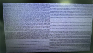
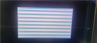
  • Static micromirror pattern persists on the DMD glass surface, resembling the projected working image (line patterns).
  • Partial functionality retained:
    • Driver board successfully identifies the DMD (valid ID readback).
    • Control commands (e.g., pattern switching) are transmitted, but micromirrors fail to flip mechanically.
  • Driver board validated: Functions normally with other DMDs, confirming board integrity.

Affected Units (Case Details):

  1. DLP3010 (Customer A – Production Line):
    • Operational duration: 1.5 years.
    • Trigger cycle: 3–5 sec intervals; exposure: ~1 sec/image set.
    • Optical parameters: 460nm blue LED @ 8A (high irradiance), but DMD temperature controlled (light-duty thermal load).
  2. DLP4710LC (Customer B – Lab Prototype):
    • Operational duration: 8 months (low usage frequency; manual triggering).
    • Exposure: ~400 ms/image set;  460nm blue LED @ ~1A; large DMD heatsink .

Attachments:

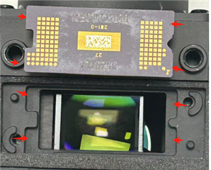
  • Figure 1: DLP3010 DMD failure pattern.

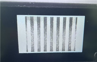
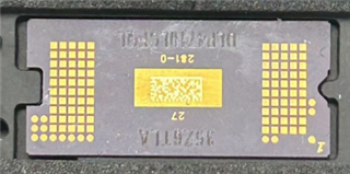
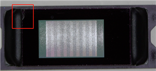
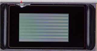
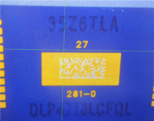
  • Figure 2: DLP4710LC DMD failure pattern + batch info.

Root Cause Hypotheses & Elimination

Primary Failure Mechanisms Considered:

  1. Incomplete micromirror reset due to abrupt power loss during operation.
  2. Mechanical/electrical lock from external interference (e.g., shock, EMI).
  3. Internal DMD circuit fault (e.g., micromirror driver IC degradation).

External Contributing Factors Evaluated:

  • a. Critical signal/power discontinuity (FPC fracture, connector dislodgement). → Eliminated:mechanical inspections confirm integrity.
    • DLP4710LC uses direct FPC connection (no adapter); 
  • b. Extreme environmental stress (temperature/vibration). → Eliminated: Stable lab/production conditions documented.
  • c. Transient noise injection (conducted/radiated). → Pending analysis
  • d. DMD degradation from prolonged high-power exposure. → Low likelihood:
    • DLP3010: High irradiance but low duty cycle; DLP4710LC: Low optical power.
  • e. Other factors.

Critical Observations & BBF Correlation Ruling

  1. Excluded BBF :
    • Artificially corrupting the LS signal (e.g., grounding/pulse injection) induced full DMD failure (unresponsive + BBF ID pattern visible), distinct from the current static-pattern behavior.
  2. DLPA3005 undervoltage protection verified:
    • Driver board ensures DMD reset within <100ms during power loss.
    • Simulated power interruptions only induced BBF faults, not micromirror sticking.

Technical Support Request

  1. Failure analysis:
    • Investigate root cause(s) for the static micromirror pattern (non-BBF, non-mechanical). 
  1. Mitigation guidance:
    • Design/process recommendations to prevent recurrence (e.g., EMI hardening, power sequencing).

Your insights are critical to resolving this field reliability issue. Thank you for your prompt attention.

Best regards.

  • Correct the above description: DLP4710LC does not use FPC to connect, but directly uses the circuit board to connect. There are DMD pin metal dots on the circuit board, and two driving chips DLPC3479.

  • Hello Junfa,

    Thanks for following up on your past issue, it's good to know you've found a resolution.

    Firstly, could you confirm these parts are the DLP3010LC and DLP4710LC? Secondly, could you provide a few more details about the systems you are using with the DLP3010 and DLP4710? Is this the only pattern that is cycled? How do these patterns fit into your patterns exposed on this DMD?

    I'll start checking with my team about this they might have more follow-up questions.

    Best,

    Aaron

  • Dear Aaron ,

    To confirm, the affected models are:

    • DLP3010 (legacy version)

    • DLP4710LC (batch information shown in the previous images)

    Regarding the two abnormal optical engines:

    1. The stuck patterns observed are not the only patterns in the system's cycling sequence. Both firmware versions store 18 patterns per set, with differences only in their configured dark/exposure times.

    2. Each defines a single pattern set (18 patterns total). The stuck pattern likely corresponds to one of these cycling patterns, as its orientation (horizontal/vertical) matches one of the projected patterns.

    Pattern Integration & Trigger Mechanism:

    • Patterns are loaded to the optical engine's Flash via DLP EVM GUI for system integration.

    • Pattern projection is triggered by:

      • An external pulse signal sent to the MCU

      • MCU then issues I2C commands to DLP347X (using "run once" function)

    • Projection frequency details:

      • 3D scanning mode: Software sends pulse signals every 3-5s → projects one full pattern set

      • Manual mode: Pulse triggered via software UI → projects one full pattern set

    Please let me know if you require additional technical specifics .

    I'm prepared to provide further documentation as needed,thank you.

  • Hello Junfa,

    I understand how the images are being produced now, thank you.

    I have yet to hear back from my team but I will press for information on this and get back to you shortly,

    Thank you again,

    Aaron

  • Hello Junfa,

    There are a few questions that my team has:

    1. When you say "low thermal load on one of the DMD,"  what is the DMD temp during operation?
    2. What is the ambient temp?
    3. What is the Blue power level (W) hitting the DMD?
    4. Is the Blue power hitting the whole DMD (including aperture, just the array or just a portion of the array)?
    5. What type of mechanical load is on the DMD (i.e. how is DMD being held against the driver board)?

    Best,

    Aaron

  • Dear Aaron ,

    We apologize but we need to simulate the actual customer usage environment - placing the optical module inside a 3D camera with passive cooling (no fan) for the DMD - to obtain accurate DMD temperature and ambient temperature measurements.

    The light power on the DMD is still being verified. These test requirements are currently in progress, and we will reply once we have the data results.

    However, based on experience, we estimate the DMD ceramic temperature of the 4710 to be around 50°C under the customer's usage environment and test conditions.

    Regarding your questions, we can confirm the following two points:

    1. The blue light continuously irradiates all glass surfaces of the DMD, including:

      • WINDOW

      • APERTURE

      • ACTIVE ARRAY
        Additionally, the blue light also continuously shines on the black encapsulant material.

    2. The DMD is not fixed to the driver board as you might have misunderstood. The DMD mounting structure is as follows:

      • First placed inside the housing

      • Horizontally fixed with adhesive rods

      • Then the connector is installed

      • Followed by the driver board

      • Finally secured vertically with screws

    Furthermore, after disassembling and analyzing the defective optical modules, we discovered additional issues:

    1. Both the 3010 and 4710 DMDs have glass damage, with the 4710 being more severe. Please refer to the images below:

    After verification:

    • For the 3010 DMD: Functional testing after assembly showed no issues before shipment. We cannot determine whether the glass damage existed before assembly or occurred during extended use - though we believe the former is more likely.

    • For the 4710 DMD: Functional testing after assembly showed no issues before shipment.
      We can confirm the DMD glass was defective before assembly. This is because the DMD was previously installed in an incompatible structure, and the glass was damaged when screws were tightened against it.. Since this unit was sent to the customer for debugging purposes, we evaluated that the surface damage would have minimal impact and approved it for special shipment.

    As we are not familiar with the DMD's internal circuitry, materials, manufacturing processes, or operational principles, we request your engineers to confirm:

    • What risks exist when the DMD glass is damaged?

    Finally, we have one more question:
    Is it permissible to expose the DMD glass, aperture, and black encapsulant material to the same light power intensity?
    I believe avoiding such exposure could improve reliability by reducing DMD array temperature, but I cannot confirm whether design modifications are necessary to prevent this issue.

  • Hello Junfa,

    I am checking with my team about the questions about glass! Please do keep us updated on the temperature evaluation!

    Could you confirm for me that the stripes you are seeing on the DMD are seen while the DMD is off?

    Best,

    Aaron

  • Hello Aaron ,

    Confirmed: The stripes remain visible on the DMD when it is powered off.

  • Hello Junfa,

    Thank you for the confirmation! These kinds of lines are common when powerdown procedure is not followed. These usually wouldn't effect performance when powered on.

    Returning to the stuck pixels, my teams thoughts are still on the glass damage and compromising the bond of the glass. It is important that this not be exposed as ambient air greatly decreases the lifetime of the device and will result as we see now.

    Please keep us informed about any evaluations you return with!

    Best,

    Aaron

  • Hello Aaron ,

    Regarding the point you mentioned, I can confirm that all our current boards follow the power-down procedure. Even if the customer directly cuts power, the DMD has sufficient time to complete shutdown.

    Additionally, we conducted a test where:

    1. The DMD was powered on and set to cycle stripe pattern projection.

    2. We forcibly disconnected the DMD connector from the DMD board while operating.

    3. The DMD maintains a fixed pattern (see image below), and it can be observed that this does not constitute a complete stripe image.

    After reconnecting and powering on:

    • The DMD booted normally

    • Micromirrors completed reset successfully

    • Could display other patterns normally

    • No additional bad pixels were observed in projected images

    We repeated this test multiple times and consistently confirmed:

    • The DMD never entered a hung state

    • No new bad pixels were generated


    Below are our DMD optical power measurement results:

    DLP3010:

    • LED current @1.5A, 100% duty: ~200 mW optical power

    • LED current @12.5A, 100% duty: ~1500 mW optical power

    DLP4710:

    • LED current @1.5A, 100% duty: ~260 mW optical power

    • LED current @12.5A, 100% duty: ~1400 mW optical power

    From this data, we deduce that during customer usage of the DLP4710:

    • Operating at 1.5A LED current

    • Manual trigger projection (variable frequency)

    • Each manual trigger projects a stripe pattern set with:

      • Optical power ≤260 mW

      • Duration ≈400 ms per trigger

  • Hello Junfa,

    Thank your for the additional information, I've reached out to my team for any comment on power but we still have concerns about the seal on the device with the cracks in the glass.

    This is definitely a package failure and pixel failures would be expected.

    Please advise if you have any investigation reports.

    Best,

    Aaron

  • Dear Aaron,

    Currently, we do not have a relevant analysis report for this issue, as we are uncertain about the appropriate methodology for investigation. If you could provide suggested directions to guide our analysis, we would appreciate it. However, please note that if specialized equipment is required, we may not be able to perform the tests, as we only have standard electronic instruments and measurement tools available.

    Regarding the temperature test, the results are as follows:

    • DLP3010:

      • Tested under the customer’s 3D camera application conditions.

      • LED current: 10A

      • Continuous triggered projection for 1 hour (all test points stabilized).

      • After 2 hours:

        • Ambient temperature of the optical module: 44.3°C

        • DMD heatsink (air-exposed) temperature: 44.8°C

        • DMD ceramic temperature: 47.4°C

    • DLP4710:

      • Testing has not yet been conducted.

      • However, we estimate that at an LED current of 1.5A, the DMD ceramic temperature should remain relatively low, likely below 45°C.

    Thank you for your support!

  • Hello Junfa,

    Sorry, I'm needing to reach out to others and there is a delay.

    Please give me until early next week to confirm information from others.

    The optical power looks to be as expected.

    Best,

    Aaron

  • Hello Junfa,

    The 2 things you're trying to do here - Failure Analysis and Mitigation are as below:

    1. Failure Analysis - you'll need to submit for Failure Analysis investigation.

    2. Mitigation - This thread can be referenced in future communication but it needs to be pointed out that optical power should not be exposed more than ~10% of the active array.

    Additionally, the blue light also continuously shines on the black encapsulant material.

    I would recommend you to look into section 6.12 and 7.5.3 of the DLP3010 datasheet and section 6.12 and 7.5.1.3 of the DLP4710LC datasheet.

    There are other members of my team that will be contacted when you reach through the Failure Analysis path but again, we can utilize this thread history going forward.

    Best,

    Aaron

  • Dear Aaron,

    Understood. I will proceed with submitting a formal Failure Analysis request through the proper channels.

    As documentation is required for the FA submission, and considering our previously mentioned limitations in analyzing the DMD component itself (due to lack of specialized equipment/methods), I will reference the technical details from this thread as the primary analysis report/documentation.

    Thank you for your support.

  • There are other members of my team that will be contacted when you reach through the Failure Analysis path but again, we can utilize this thread history going forward.

    Dear Aaron,

    I regret to inform you that my FA submission was rejected due to the devices exceeding the 1-year warranty period.

    While we fully respect TI's standard policy, we kindly request your team's support to continue analyzing this issue for technical research purposes. If deemed appropriate:

    1. Please advise if alternative paths exist (e.g., paid FA or technical collaboration process)

    2. Or designate a contact point, and we will promptly provide:

      • Complete test data (including video evidence)

      • Non-failed units from the same batch for comparison

    The observed [micromirror sticking/glass damage] has critical reliability implications. Your expertise would be invaluable to us.

    Thank you for your consideration.

  • Hello Junfa,

    I understand reading back through the discussion that some units were known to have cracks and were going to have issues. As I've explained before, exposing the mirrors to ambient air will cause them to stick.

    Could you advise how many units you're seeing issues with? Are these previously known issue parts?

    My last comment highlighted that the overfill of light should not be more than ~10% of the active array. The black encapsulated material should not ever have light illuminated on it. This would cause unknown issues and this is outside of specified testing parameters but I'd think the encapsulation material would degrade.

    What kind of investigative FA request were you thinking of submitting for? Both DLP3010LC and DLP4710LC?

    Best,

    Aaron

  • Dear Aaron,

    Understood and acknowledged.

    Here’s the confirmation:

    1. Failure Quantity: 1 unit each for DLP3010 and DLP4710LC

    2. Root Cause Assessment:

      • Strong correlation with glass damage

      • Excessive light overfill (>10% active array) is the most probable cause

    Regarding FA submission:

    • This request focuses only on DLP4710LC (per this thread’s scope)

    • We’re aware this unit exceeds the 1-year warranty period

    If TI cannot process out-of-warranty FA cases through any alternative channels, kindly advise. We’ll then close this case accordingly. Appreciate your support!

    Best regards,
    Junfa Ye

  • Hello Junfa,

    I'm checking with my management how I can help. Unfortunately, a few people are out of office until next Tuesday, please give me time to confirm with them.

    I'll need to hear back on how to proceed.

    Best,

    Aaron

  • Dear Aaron,

    Thank you for the prompt follow-up. We fully understand and respect TI's process arrangements. After your team returns next Tuesday, kindly help confirm the handling plan for these key items:

    1. Special FA submission path for out-of-warranty cases (if any)

    2. Feasibility analysis for DLP4710LC glass damage failure

    3. TI-validated method to verify light overfill

    We remain on standby for your update.

  • Hello Junfa,

    I'll get back to you on #1-#2.

    #3 - Overfill verification:

    Since TI is not a Optical manufacturing company, we don't deal with illumination much, but our best method for estimation is to make a stencil (again estimation) which is ~10% larger than the DMD active array area and place this where the DMD would typically be mounted. This will show what stray light is outside of the active array.

    It is understood that different types of Optical stack-ups can produce different patterns of illumination and could change the shape slightly, this is why it is an estimation.

    Best,

    Aaron

  • Hello Junfa,

    Sorry for the long delay on this, things have been piling up these past few weeks and I had to get more information about this.

    The consensus from my management is that the parts are outside the warranty period and the glass damage is already understood and seen. FA is not going to tell us anything different than what we already know and will not be worth pursuing.

    There are 2 notes I related to this issue and should be fairly straightforward:

    1.  damage on the glass indicates damage on the seal, any exposure to ambient air will cause pixels to stick.

    2. illumination outside of the array area >> 10% overfill and onto epoxy area (encapsulant) and moisture may be being allowed into the package - again causing pixels to stick.

    In summary, the FA for these devices would entirely come back as say "mechanical damage to the window resulted in moisture ingress" and it would be done. There isn't much discovery in the DMDs if they're known to be damaged. If the devices are not visibly damaged FA is more feasible.

    Thank you again for your patience and best of luck on future implementations.

    Best,

    Aaron

  • Dear Aaron,

    Thank you for your detailed explanation and technical recommendations. We fully understand TI's assessment conclusions.

    Moving forward, we will optimize the identified issues accordingly.

    Best regards,

    Junfa