This thread has been locked.

If you have a related question, please click the "Ask a related question" button in the top right corner. The newly created question will be automatically linked to this question.

DLP2021-Q1: DLP2021AFQUQ1

Part Number: DLP2021-Q1
Other Parts Discussed in Thread: DLP2021AM263Q1EVM

Tool/software:

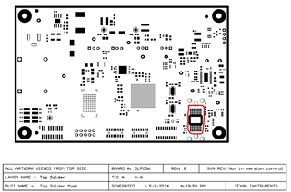
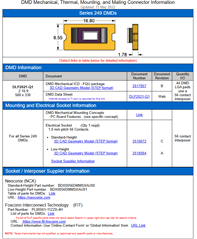
1、Is the DLP2021AFQUQ1 device produced by reflow soldering or by locking onto the PCB board?

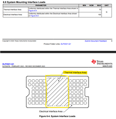
2、Is the hot pad area of DLP2021 directly exposed copper on the PCB? Or is heat dissipation achieved by adding a thermal conductive silicone pad in the structure?

  • Hi Kerwin,

    1. Please see the S249 DMD mounting concepts page that I found off the DLP2021-Q1's product page.  This shows that the DLP2021AFQUQ1 DMD is uses a mechanical assembly that requires compression.


      1. Note the cutout region above, as it pertains to Question 2 below.
    2. Are you talking about the center pad of the DLP2021-Q1 marked as "Thermal Interface Area" below?  If so, this is not electrically connected to the PCB. In fact, a lot of our DMD boards will have a cutout region there. You can see the layout via our DLP2021-Q1's reference design files or EVMs via the Hardware development tab of the product page.  To give a brief answer here, this appears to be a cutout that is exposed.  There is no thermal conductive silicone pad, and this is not copper on the PCB. This allows you to, again, attach thermal couples with ease if you wish to do so.

      1. You can see that the board dimensions on our DLP2021AM263Q1EVM, for example, has a cutout in its board geometry for that thermal area where you may connect a thermocouple.  This is taken from the gerber file you may find on the EVM page's design files.
      2. Here is an example of the top solder for your reference. This can be found in the design files on the DLP2021AM263Q1EVM layerPlots PDF.

        Note the mounting holes above and below the DMD area.
      3. Below are images of the EVM I mention above.

    Regards,
    Michael Ly

  • Kerwin,

    Just adding to this in case there is confusion in the future. The first image above shows download links for the mechanical-electrical interface, which is how the DMD is mounted to a PCB via a mechanical interface.

    When you download DLPR103, which is our literature number for the assembly, you will see the following when you unzip the archived file:

    Please open the README html file in your web browser.

    Follow the Getting Started directions carefully and use the provided link in step 4 to guide you to another page that shows suppliers of the mechanical components used to attach the DMD to the PCB.

    The link in step 4 from the Getting Started guide leads you to this webpage (local to just your machine because you downloaded our html file)

    This page has additional links to help you order correct parts for attaching the DMD to your board whether it be a custom board or one of TI's EVMs.

    Please let me know if you have any additional questions! Thank you.

    Regards,
    Michael Ly