This thread has been locked.

If you have a related question, please click the "Ask a related question" button in the top right corner. The newly created question will be automatically linked to this question.

LED modulation by external gating signal

Hi, for an application I'm considering for Logic Light Commander, would be ideal to modulate the LEDs according to an external reference signal (<50KHz with LED active times <20us).

1. Would this be possible, independently from the pattern data source (DVI,exp pattern or static buffer), system operation mode (video or structured light) or frame trigger settings?

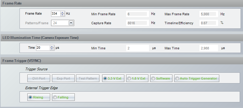
2.  What kind of connections and circuit should I make in order to use the 3.3V external trigger for frame triggering?

Thanks

Marco

  • Hi Marco,

    Sorry, I am not able to understand your question completely.

    What do you mean by "modulate the LEDs according to an ext times < 20us)" ? Is it a trigger input signal to the LightCommander or is it about the LED_EN signal going to LED Driver? 

    Can you elaborate more on your application?

    If possible please show in picture or signal diagram.. this will help us to understand better.

    Regards,

    Sanjeev

  • 1817.LED modulation signal.pptx

    Hi Sanjeev, thanks for your reply.

    I realized my post was not really clear.

    I'd like to synchronize the light emission of the DLP with an acquisition system  so that the DLP is illuminating the sample only during the detection dead times (tipically lasting 20us every 3ms) to avoid detection contamination.

    In the first question I was asking about the possibility to use external signal like the one reported in the ppt  going to LED driver directly as LED enable , controlling carefully the timing of light emission, avoiding to work on the pattern triggering to have the same result, because I don't really need a high pattern refresh rate.

    One side note,  is LED strenght signal encoding the pulse width modulation of the LED intensity? 

    is there any way to work on this line to achieve the same result?

    An alternative to the above solutions, it could be to use the same signal as external triggering 3.3V for the pattern presentation althought in this case the pattern sequence has to be carefully arranged and so I'm asking about the circuit modifications/connections to work with 3.3V external trigger  the light commander.

    Thanks for your time

    Best

    MArco

  • Hello Marco,

    Thank you for sharing the timing diagram. 

    is there any way to work on this line to achieve the same result?

    If I understood your question correction, I think what you are asking can be done as it is. 

    Couple of important things.

    1. In your timing diagram the period of sample lasting is mentioned as 21us to 3ms. 21us period is not possible, DMD takes about ~200us to load the image data. So your period can be any value within range 0.2ms to 166.67ms.

    2.  At 3ms period you can simply change the LED illumination time to 20us and then build the sequence this will work for you without any additional changes. Attached is the snap-shot of the LightCommander GUI. 

    Frame Trigger (VSYNC) can be selected as 'External trigger' or 'Auto-Trigger'.  With 'External Trigger' - your acquisition system can provide the trigger input the system. So the DLP illumination precisely illuminate the sample for 20us after receiving the trigger.

    Further on your specific questions - 

    One side note,  is LED strenght signal encoding the pulse width modulation of the LED intensity? 

    [Sanjeev] In the LightCommander Kit the LED Driver used is advanced once, it accepts the LED strength information via SPI interface. 

    If you would like to share the details about your end application with me, you can send me a friend's request. We can take it offline.

    Regards,

    Sanjeev