


Hi,
I am trying to output from GPIO0, but even after reading the documentation and a few forum posts, I still can't make it work.
The forum posts in question are these:
The pin numbering described in the second link is wrong. I found the correct ones in the following document:
www.ti.com/.../tidr157.pdf (page 5, and the pins are mirrored since it is from a pandaboard's point of view)
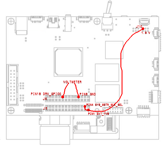
So here is the connection layout I thought would work:
I connected J3 pin 1 (EXT_1v8) to a 1.8v source on J10. I bridged it to J3 pin 4 (SYS_MASTER_MUX_SEL) to enable level shifting.
I connected pins 18(gpio0) and 8(gnd) of connector J6 to a voltmeter hoping to see the voltage vary according to the changes I make in the peripheral control section lightcrafter control software.
I have found that connecting any voltage source to J3 pin 1 (EXT_1v8) disables USB communication to the computer. The device litteraly disappears from the list if I do 'lsusb' on linux, and of course the Lightcrafter control software cannot connect either.
Where have I gone wrong? Should I do something with J3 pin 22 SYS_USB_SEL? It is left unconnected, so I assume it is set to low and therefore the usb should not be routed to the non-existing pandabord.
Any insight would be appreciated.
thank you,
Louis Bouchard


