Other Parts Discussed in Thread: DLPC2607
Tool/software: Linux
I am working on the integration of the Raspberry Pi and see that there are 3 main steps
1) Configure for software I2C on BCM Pins 23 and 24 (since DPI parallel video output will use the default hardware I2C pins). The following pinout information is useful https://pinout.xyz/pinout/dpi. Note that connections I used were 20cm Dupont connectors and I didn't use any pull-up resistors for the I2C. The original I2C pin mappings for hardware I2C on the Raspberry Pi has relevant pullups added to the circuitry and I'm not sure if they are configured using internal pull-ups or not in the below configuration steps. If you are having troubles with I2C, you can either try using a short wiring connection for the I2C pins, or else you might need to add 1.8k pullup resistors on the Raspberry Pi for BCM Pins 23 and 24 (i.e. physical pins 16 and 18 on the Raspberry Pi), where the software I2C has been re-mapped to, in support of RGB666 output).
2) Wire up DPI parallel Video pins, as per the 24-bit (RGB888) mapping of https://elinux.org/24bit_LCD_for_BBB (note that we are wiring up as per the RGB888 definitions, but only going to use pins R2-R7, B2-B7 and G2-G7, i.e. not connecting R0,R1, B0,B1 and G0,G1 pins. For the Raspberry Pi we need to define the mapping as 18-bit (RGB666), referenced as Mode 5 here, and then connect the relevant pins across on the DLPDLCR2000EVM module.
Here is my pinout showing the Raspberry Pi Connector (pin 1 is top left i.e. the unconnected 3.3V pin) and the references for the relevant pin connections on the DLPDLCR2000EVM, on connectors P1 and P2, as described in Figure 13 of the user guide http://www.ti.com/lit/ug/dlpu049c/dlpu049c.pdf. The connections are given as the connector reference and then their physical pin number and description, as per Figure 13 of the user guide.
| P1: 27 VSYNC | |
| P1: 29 HSYNC | |
| P1: 16 Data17 | P1: 38 Data9 |
| P1: 36 Data10 | |
| P1: 45 Data0 | P1: 46 Data1 |
| P2: 20 EX_SDA | |
| P2: 19 EX_SCL | |
| P1: 42 Data5 | |
| P1: 32 Data15 | |
| P1: 39 Data6 | P1: 31 Data14 |
| P1: 33 Data13 | |
| P1: 28 PCLK | P1: 30 DATAEN |
| P1: 34 Data11 | |
| P1: 35 Data12 | P1: 40 Data7 |
| P1: 37 Data8 | |
| P1: 43 Data2 | P1: 15 Data16 |
| P1: 44 Data3 | |
| P2: 46 GND | P1: 41 Data4 |
3) Define the video format for output in the file located in /boot/config.txt in the OS e.g. Raspian Jesse.
Steps and 1 and 2 are fine, however I am stuck at the final part, step 3, and I need some help for the parameters required to define the video output.
According to the reference https://www.raspberrypi.org/documentation/hardware/raspberrypi/dpi/README.md the Raspberry Pi uses the /boot/config.txt file to define an overlay and video timing parameters. I find the overlay rgb18.dtb exists in the overlays directory of my Rapsbian Jesse install, so can reference that to define the pin mappings, but then there are two more critical lines of information that I need to supply to configure the video output, and these need detailed video timings and configuration parameters.
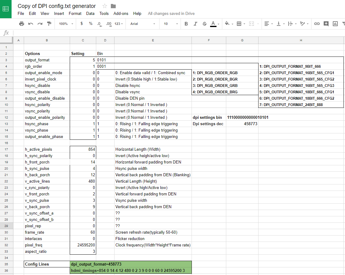
The first line to define is the dpi_output_format, which is generated from a concatenated sequence of bits, resulting in a single number value. The options and their relative bit positions are as follows
| Options | Bit Position |
| output_format | 0:3 |
| rgb_order | 4:7 |
| output_enable_mode | 8 |
| invert_pixel_clock | 9 |
| hsync_disable | 10 |
| vsync_disable | 11 |
| output_enable_disable | 12 |
| hsync_polarity | 13 |
| vsync_polarity | 14 |
| output_enable_polarity | 15 |
| hsync_phase | 16 |
| vsync_phase | 17 |
| output_enable_phase | 18 |
The values are selected from the following possible options values;
output_format:
   1: DPI_OUTPUT_FORMAT_9BIT_666
   2: DPI_OUTPUT_FORMAT_16BIT_565_CFG1
   3: DPI_OUTPUT_FORMAT_16BIT_565_CFG2
   4: DPI_OUTPUT_FORMAT_16BIT_565_CFG3
   5: DPI_OUTPUT_FORMAT_18BIT_666_CFG1
   6: DPI_OUTPUT_FORMAT_18BIT_666_CFG2
   7: DPI_OUTPUT_FORMAT_24BIT_888

rgb_order:
   1: DPI_RGB_ORDER_RGB
   2: DPI_RGB_ORDER_BGR
   3: DPI_RGB_ORDER_GRB
   4: DPI_RGB_ORDER_BRG

output_enable_mode:
   0: DPI_OUTPUT_ENABLE_MODE_DATA_VALID
   1: DPI_OUTPUT_ENABLE_MODE_COMBINED_SYNCS

invert_pixel_clock:
   0: RGB Data changes on rising edge and is stable at falling edge
   1: RGB Data changes on falling edge and is stable at rising edge.

hsync/vsync/output_enable_polarity:
   0: default for HDMI mode
   1: inverted

hsync/vsync/oe phases:
   0: DPI_PHASE_POSEDGE
   1: DPI_PHASE_NEGEDGE
The second line to define is the hdmi_timings, which is a sequence of space-separated parameter values in the following format,
hdmi_timings = <h_active_pixels> <h_sync_polarity> <h_front_porch> <h_sync_pulse> <h_back_porch> <v_active_lines> <v_sync_polarity> <v_front_porch> <v_sync_pulse> <v_back_porch> <v_sync_offset_a> <v_sync_offset_b> <pixel_rep> <frame_rate> <interlaced> <pixel_freq> <aspect_ratio>

Where
<h_active_pixels> = horizontal pixels (width)
<h_sync_polarity> = invert hsync polarity
<h_front_porch>   = horizontal forward padding from DE acitve edge
<h_sync_pulse>    = hsync pulse width in pixel clocks
<h_back_porch>    = vertical back padding from DE active edge
<v_active_lines>  = vertical pixels height (lines)
<v_sync_polarity> = invert vsync polarity
<v_front_porch>   = vertical forward padding from DE active edge
<v_sync_pulse>    = vsync pulse width in pixel clocks
<v_back_porch>    = vertical back padding from DE active edge
<v_sync_offset_a> = leave at zero
<v_sync_offset_b> = leave at zero
<pixel_rep>       = leave at zero
<frame_rate>      = screen refresh rate in Hz
<interlaced>      = leave at zero
<pixel_freq>      = clock frequency (width*height*framerate)
<aspect_ratio>    = *

* is the aspect ratio, represented by one of the following numbers.
HDMI_ASPECT_4_3 = 1
HDMI_ASPECT_14_9 = 2
HDMI_ASPECT_16_9 = 3
HDMI_ASPECT_5_4 = 4
HDMI_ASPECT_16_10 = 5
HDMI_ASPECT_15_9 = 6
HDMI_ASPECT_21_9 = 7
HDMI_ASPECT_64_27 = 8
So I am seeking help to compile the relevant information to populate the dpi_output_format and hdmi_timings values. Note that at http://blog.reasonablycorrect.com/raw-dpi-raspberry-pi/ there is a useful spreadsheet which you can copy and edit, to easily generate the resulting parameter values.
I notice that in document DLP2607 sections 6.8-6.12 there are some parameters discussed, but it gives min/max rather than the specific values used in the DLPDLCR2000EVM.
Perhaps there is some similar information supplied/defined when setting up the Beagle Bone Black integration that can be referenced?
I hope you can help with filling in the relevant information!
Thanks,