This thread has been locked.

If you have a related question, please click the "Ask a related question" button in the top right corner. The newly created question will be automatically linked to this question.

DLPLCR6500EVM: DMD Illumination Angle

Part Number: DLPLCR6500EVM

Hello,

I would like some clarification for the angle in which the illumination of the DMD should be done to get a horizontal beam. I have already seen the datasheet and this document (www.ti.com/.../dlpa022.pdf) but it is still not very clear for me.

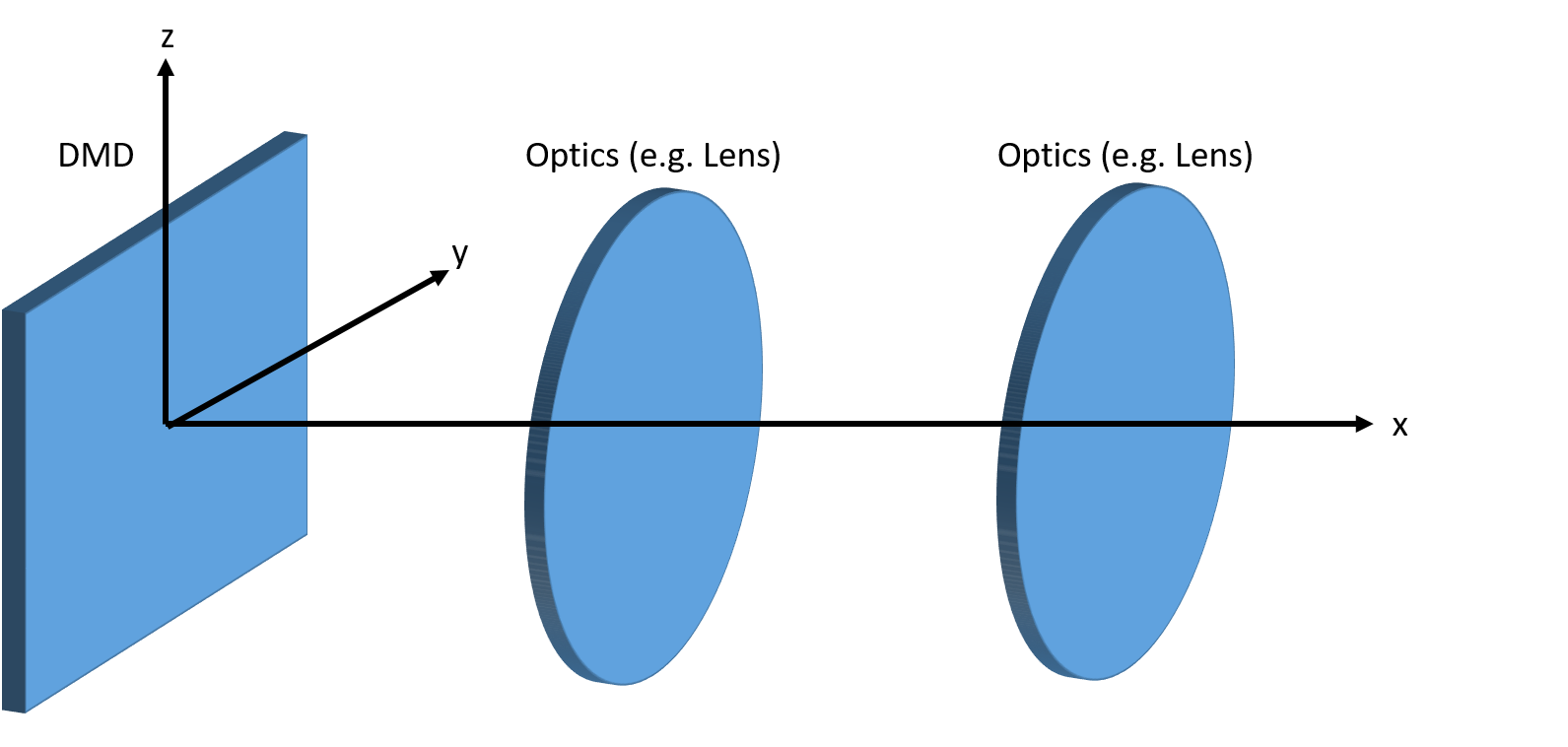
Could you please let me know in terms of cartesian coordinates, where the 24 and 45 degrees are oriented? Here is a schematic so that we have the same reference.

So my optical axis here is in the x-axis. Right now I'm confused if the illumination should come at angle of -45 degrees between x and y, i.e. rotate the illumination source towards the negative y axis, and then 66 degrees between x and z (so that the source is 24 degrees away from the z axis); or if it should be -24 between x and y, and 45 between x and z, or if it is another configuration. Please let me know the correct configuration to get a beam in the x-axis.

Thanks!

  • Hi Khaled,

    As you may know, typical illumination is done 24° (2X the tilt angle) from the vertical and -45° azimuth from the vector toward the top of the DMD (as shown in Figure 12 of the data sheet). This will result in the projected beam for the "on" state being normal to the DMD window. There is only one corner (pin 1 with the notch) of the DMD at which the illumination enters the DMD at 45 degrees (to be normal with the micromirror hinge axis) which may help with your orientation. The best visual aid would be to follow the diagram from Figure 14 on pg. 29 of the datasheet where you have the corner illumination angle at pin 1 to be 45 degrees and then relative to “A” the illumination is 24 degrees. If you would like to use your own axis, it may help to label the axes onto this diagram and go from there.

    I hope this helps,

    Taylor
  • Thank you for your reply.

    So if I am looking at the DMD, the illumination would be shining on the top left corner (the -45 degrees) and then with an angle of 22 degrees towards me, is this correct? If not, I really would appreciate a more clear explanation than "from the vertical and from the azimuth", as I am not sure which axis you consider vertical and azimuth.

  • Hi Khaled,

    I believe you are correct, but rather 24 degrees than 22.

    Best Regards,

    Taylor
  • It seems that wasn't the correct configuration. Could you please clarify using a diagram where the light should be illuminated, or to explain more clearly what you consider to be the "vertical" and the "vector toward the DMD", so that I am able to understand which is the correct angle?
  • Hello Khaled,

    Please refer to the following Application Report:  DLP System Optics Application Note 

    Particularly Figure 9 which shows how elevation angle is measured (it is from the normal vector (vertical - or "z" axis) relative to the DMD array.  And it also shows how azimuth is measured.  For clarity the "plane of constant azimuth" shown is pointing toward pin 0 on the DMD.

    Also, refer to the DLP6500 0.65 1080p MVSP S600 DMD datasheet (Rev. B) - particularly Figure 12 which shows the illumination corner,  the illumination 45° from the x or y axis as shown in the figure.

    FIzix

  • Thank you very much for your reply. It is a lot clearer for me now. However, now to my understanding, according to figure 9 in the system optics application note, wouldn't -45 degrees azimuth mean that the illumination is entering at the top right corner, not the top left? It seems to me that in this drawing it would be -135 degrees instead. Or am I misunderstanding?

  • Hello Khaled,

    In Figure 9 of the System Optics Application Note the drawing the DMD is rotated so that the top is pointing toward the viewer. The salient point is that the azimuth is coming from the pin 0 location at ±45° from the vertical or horizontal axis (The 45° is actually |Φ| ). Figure 9 of the System Optics Application Note can be a little confusing, but the datasheet Figure 12 should make it clear.

    Fizix