This thread has been locked.

If you have a related question, please click the "Ask a related question" button in the top right corner. The newly created question will be automatically linked to this question.

DLP4500: Question regarding lens arrangement in LightCrafter4500 iView Engine and capability for generation of diffraction patterns

Part Number: DLP4500


Hello, I am interested in making modifications to the LightCrafter4500 iView Engine so that I can generate diffraction patterns from a point light source.

There is a lot of information about the iView Engine at the following page but it appears to be missing a description of some of the internal lens/windows and the role they play.

e2e.ti.com/.../278008

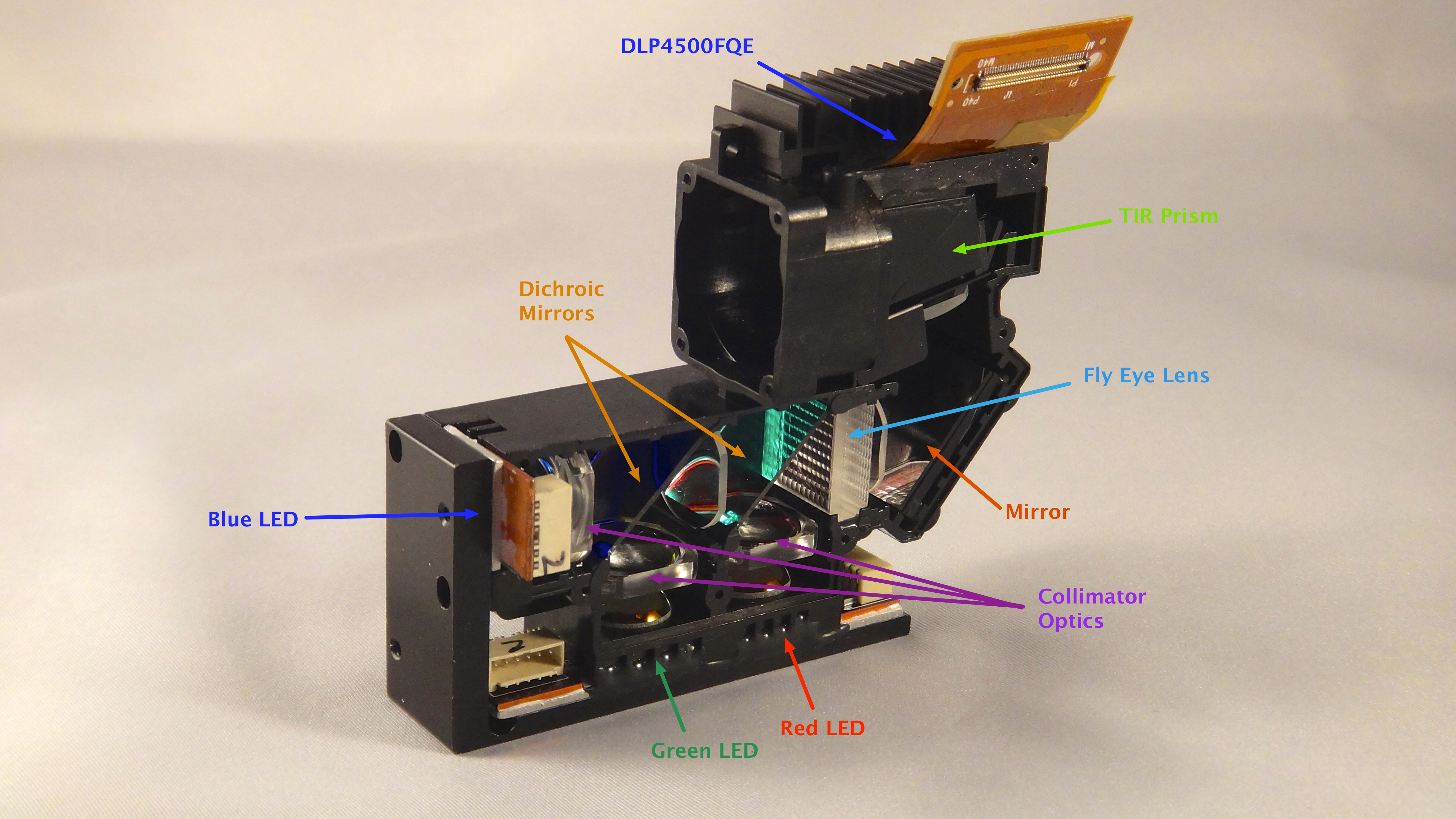
"Each LED has an optical collimator to collect the wide beam of light from the LED and produce a narrower beam. This narrow beam of light passes through a set of dichroic mirrors that reflect a specific color of light while letting other colors of light pass through it. The dichroic mirrors recombine the different colors of light  into one co-linear beam. The recombined light passes through a fly-eye and condenser lens that provides uniform light intensity. The light bounces of a mirror and passes through a total internal reflection (TIR) prism. The light is directed towards the DLP4500 DMD and goes through the focus optics."

https://e2e.ti.com/cfs-file/__key/communityserver-discussions-components-files/850/2577.Components.png

Between the dichroic mirrors there is an additional lens that no mention is made of, and immediately after the fly eye lens but before the prism there are two lens' but only one condenser lens is mentioned.

I'm trying to understand the role of these extra lens' given that the light beam should be collimated after the first collimator for each led. (Perhaps they are simply to deal with the fact the light is not truely collimated as the LED is not a point source and thus needs intermediary lens to prevent too much divergence of the light?)

If I understand correctly in order to generate diffraction patterns assuming the light is collimated passing from the led collimators to the condenser, it should be sufficient to turn one LED into a point source LED (by masking with a pinhole for example) and remove the fly-eye lens and I should be able to shine coherent light on the DMD and generate diffraction patterns. However I'm uncertain what if any effect the above lens' have on my ability to do this. If they are refocusing the light multiple times and the light is not truely collimated then removing those lens as well as removing the fly-eye lens may interfere with the condensers ability to focus the light onto the DMD if it were truely collimated from a point source.

Any input or guidance further detailing what the role of these additional lens' are and/or the feasibility of modifying the light engine as I desire, would be very much appreciated.

I expect the distances between the various lens' distances may have been precisely tuned to deal with the imperfect collimation of the current LED light sources, in which case I'm just hoping that using a true point light source will simplify things to the point where I don't need to worry too much about things and it may just work. (call me an optimist :))

  • I'de still very much be interested to know the role of the additional lens' I mentioned above. I have however decided that I don't actually need to use diffraction patterns to achieve my end goal. which is projecting diffraction limited alternating stripe patterns into the focal plane of a microscope. I was originally planning to do what I had read in various university papers and generate a diffraction pattern then filter only the 1st order before passing them to the microscope.

    It seems I may just need to make a replacement lens for the lightcrafter 4500 to remove the 100% offset and center it at a 0% offset, then scale it and focus it into the focal plain of the microscope. Can anyone tell me the way to remove the aluminum base plate from the projector? I am guessing that the base plate helps act as a heat sink for all the LED and DMD heat. But provided adequate cooling would it be possible to 3d print a replacement base plate? If not I can probably dremel out part of the existing base plate thus allowing me to mount the lens lower and eliminate the 100% offset.

    I'm guessing that the space available for the replacement lens assembly will be restricted in it's maximum diameter as the light engine is already right up butt against the side of the current lens, but I should be able to at least lower it down to eliminate the 100% offset it currently has, then experiment with making a replacement lens that allows me to focus and scale the image as necessary.

    If there are any threads which have information from other users attempting similar things that you are aware of please let me know.

    Also I would still like to know the role of those additional lens' in the future, incase I decide to try and switch to a laser light source to improve contrast and focus in the future.

    Thanks!

  • Peter,

    Thanks for the detail in your inquiry. Also, welcome to the E2E forums and thanks for your interest in our DLP technology.

    I'd like to note that you may run into problems switching to a laser light source, as the DLP4500 DMD is not rated for laser sources. In particular, you should check the part datasheet for exactly what the device can tolerate in terms of energy directed at the mirrors.

    As for your questions about the mirror configuration, I'll loop in some experts from my team to give you a suitable response within a few days. Thanks for your patience.

    Best Regards,
    Philippe Dollo
  • Hey Philippe,

    Thanks I would appreciate any additional information you can give regarding the lens configuration in the light engine.

  • Hi Peter,

    Since the light engine is manufactured by iView, I'd request you to kindly contact iView for more information on this regard. 

    Thanks & Regards,

    Hirak.

  • Thanks TI, I doubt they are going to give me any useful information but perhaps I will contact them.

    Regarding my original question about the role of the additional lens' in the light engine, I found a patent online that explains the roles of all lens' in an equivalent projection system using a fly-eye lens.

    patents.google.com/.../en

    For anyone curious see claims 12 and 13 at the end of the document.

    "12. The optical engine according to claim 11, comprising a common lens disposed between the first mirror and the second mirror, relay lenses configured to collimate light beams having passed through the fly-eye lens, and a total internal reflection prism configured to output light beams to the projection lens.

    13. The optical engine according to claim 12, wherein the relay lenses include two lenses disposed so as not to be parallel with each other."
    This patent is from LG and for a special variation of the regular fly eye lens used in the iView projection engine as far as I can tell. As such some of the claims will not apply exactly but a more general interpretation most likely matches.
    Also incase anyone else is looking it appears the iView engine used in the EVM4500 is the following. (once again this is not verified by anyone)


  • Hi Peter,

    Thanks for sharing this information with the community, and for your interest in TI DLP Technology. Have a great day!

    Thanks & Regards,
    Hirak.