This thread has been locked.

If you have a related question, please click the "Ask a related question" button in the top right corner. The newly created question will be automatically linked to this question.

C6670's CVDD pin is short to GND

Expert 2985 points
Other Parts Discussed in Thread: UCD9222, UCD7242, UCD74111

Hi all,

On my custom board, before all the chips are soldered, the CVDD pin is not short to GND.

But after all the chips are soldered, the C6670's CVDD pins and CVDD1 pins are short to GND with resistor less than 1 Ohm under multimeter test.

And the 1.8V IO, 1.5V IO and 0.75V IO is not short to GND.

Does it mean the C6670 is damaged??

Can anyone offer me the normal resistor value between CVDD/CVDD1 of C6670 or C6678 and GND??

Thanks!!

Regards,

Feng

  • Hello Feng,

    Please refer below thread for normal resistance value between CVDD and GND.

    e2e.ti.com/.../184422

    Was there any physical shorts on the pads ? In how many boards you are facing this issue ?

    Regards,
    Senthil
  • Hi,

    Unfortunately, I just soldered one board. So I can not compare with other boards at this moment. I will solder more later before I clarify this problem.

    When I open the link you attached, it show me like this

    How can I get access to this resource directly?

    Thanks!

    Regards,

    Feng

  • Feng,

    I believe what you are seeing is not real.  You refer to it as a short when it is not. I recommend that you take your multimeter and measure the resistance between CVDD and VSS on a known good board such as an EVM.  I believe that you will see the same thing.

    You are probably using a common, hand-held, portable multi-meter.  This operates on a battery that is usually 1.5V.  When you are measuring the resistance, this 1.5V supply is applied to the probe tips in series with the meter movement / sensor.  The current through the meter probes is then used to calculate the resistance between the probe tips.  The CVDD voltage on the C6670 is less than 1.5V (nominally 1.1V or less).  Therefore, when you try to measure the resistance from CVDD to VSS after the C6670 is attached, you are applying this battery voltage to the board.  Since the CVDD supply is less than the voltage supplied, the C6670 CVDD circuitry begins to power up.  This draws a lot of current from the multi-meter which makes it display a very low resistance. This low resistance is less than a true short.  The resistance displayed will be much lower when the 2 probe tips are touching.

    I hope this helps.

    Tom

  • Senthil,

    The above link is an INT-E2E link and it is not correct.  I will post a correction to that thread.

    Tom

  • Hi Tom,

    Thanks for your replies.

    1. I had test one known good board(not the EVM, just another), the resistance between C6670's CVDD and VSS is around 8 Ohm. But on my board, I got the resistance value that is less than 1 Ohm with the same test equipment(hand-held multimeter) and the same method.

    I think the resistance value less than 1 Ohm is so low that makes me believe that this is short.

    Furthermore,  in my design, I used the UCD9222 to control two UCD7242 simultaneously to generate 20A MAX output current. My I power up my board, the UCD9222 GUI reports me that there is the fats oc fault or oc fault and then the channel of UCD7242 is shutdown.

    I think it is short between CVDD and VSS, so the CVDD current will be over the limits and then the UCD9222 will shutdown the UCD7242's channel.

    Is my speculation OK?

    2. Your answer to the much lower resistance between CVDD and VSS when the 1.5V multimeter voltage is applied is great.

    But there are some question confuse me also.

    If I switch the red probe to touch the VSS pad and the black probe to touch the CVDD pad, the internal circuit between CVDD and VSS will not be powered up because the wrong voltage direction. But in this situation, why can I get the same much lower resistance?

    Regards,

    Feng

  • Feng,

    You are working with old recommendations if you implemented a 20a supply by using both channels of a UCD7242.  I would have recommended use of the UCD74111 power stage same as implemented on the C6670 EVM.  However, your implementation is valid and supported by the fusion software.

    Testing the CVDD supply with a multi-meter will always yield a low resistance.  Different meters may read different values.  I often see this resistance as less than 1 ohm.  However, this is not the same as a short.  A short reads the same as when the probes are touching.  Our multi-meters read 0.2 ohms when the probes are shorted.

    Reversing the probes will still result in a low resistance.  In this case there are diode junctions that are forward biased when the red probe is on VSS and the black probe is on CVDD.  Reversing the probes applies a voltage that violates the chip specifications.

    Tom

  • Hi Tom,

    Thanks for you further explain to result of the much lower resistance, that is very helpful.

    But now a very very strange question occurs.

    As I say previous,  on my board the resistance between CVDD and VSS is less than 1 Ohm and the resistance between CVDD1 and VSS is also.

    But after I do some software changes on the fusion software, now the CVDD1 can generate 1.0V and the resistance between CVDD1 and VSS is around 11 Ohm.

    The value is less than 1 Ohm previous but now is 11 Ohm and regualted voltage output is OK after I just change the UCD9222's configuration.

    However, the CVDD resistance remains less than 1 Ohm that I do not consider this value as a short now.

    Because the schematics of CVDD and CVDD1 are the same, I copy the CVDD1 configuration of UCD9222 to CVDD channel. But CVDD has no output and resistance remains much lower and UCD9222 reports FLT.

    I see the C6670's errta which shows me that CVDD must be powered up with 1.1V initially. But I just ignore the VID and configure the CVDD as 0.95V.  Is it the reason why CVDD is not correct?

    Could you give me some advices?

    Regards,

    Feng

  • Feng,

    I recommend that you debug the power supplies on a board that does not have a C6670 mounted.  You can add resistors on the main power supplies as needed to make them stable.  This way you can separate the behavior of the supply from that of the SOC.  Once you have a working power supply solution, then you can debug the board containing a C6670.

    Tom

  • Hi Tom,

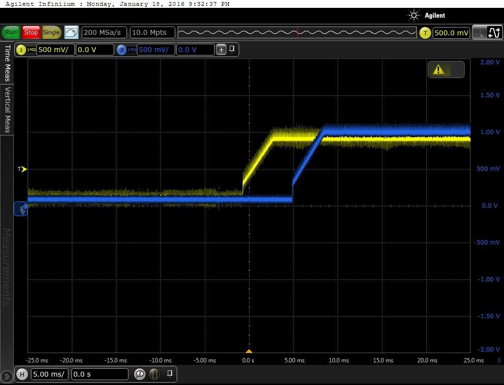
    I had removed the C6670 and debug the UCD9222+UCD7242 with 500 Ohm resistor as the UCD7242's output load. And the CVDD and CVDD1 are OK as follow

    The yellow line is CVDD with 0.95V and the blue line is CVDD1 with 1.0V.

    So I think the UCD9222+UCD7242 work well to generate CVDD and CVDD1. The schematics is 8371.CVDD_CVDD1.pdf

    But after I solder one new C6670 chip(with the lot trace of YB20 not YB20C)  and before the board is powered up, I measure the resistance between either CVDD or CVDD1 and GND is 0.2 Ohm and I got the value of 0.2 Ohm when I directly touch the two probes of the hand-held multi-meter together. So I think there is something wrong about this C6670 chip. The same question is in e2e.ti.com/.../484532.

    For comparison, I got the resistance between CVDD and VSS is about 10 Ohm and resistance between CVDD1 and VSS is about 16 Ohm on EVM6670L.

    So I think the 0.2 Ohm of either CVDD or CVDD1 to GND is not normal. Am I right?

    Furthermore, when I powered up the board, the UCD7242 reports FLT to UCD9222.

    1. I mean that the UCD9222+UCD7242 work well  on my custom board without C6670 soldered. After C6670 is soldered, however, the UCD7242 reports FLT. I think it must be short and the current ramps too high to reach the UCD7242's limits and then UCd7242 reports FLT. Am I right?

    2. I had used two C6670 on my custom board, I met a very strange phenomenon. When the first C6670 is used, I got the value of 0.2 Ohm between CVDD1 and GND. And after I powered up the board, the resistance remained  around 0.2 Ohm. But after I did some changes about the UCD9222's configuration, the CVDD1 is OK and then I got the resistance of CVDD1 and GND is around 16 Ohm.

    I mean that the resistance between CVDD1 and GND is 0.2 Ohm at first time. However, I got the new resistance value of 16 Ohm after I did the configuration changes of UCD9222. Is it normal? I can not reproduce this phenomenon after I soldered one new C6670 chip.

    3. All these questions are under the condition that I used the C6670 with YB20 as lot trace. But I think the YB20C(as indicated in the table 1 of C6670's errata) is normal. So please help me to confirm C6670 with YB20 is OK or not. The same question is in e2e.ti.com/.../484532.

    Regards,

    Feng

  • Feng,

    1.  Using a 500-ohm resistor is not a real load for this design.  You need a load on CVDD in excess of 5A.  I recommend that you attach a 1-ohm resistor to CVDD1 and multiple 1-ohm resistors on CVDD.  Alternately, there are programmable-load test devices that can be used.  You should validate power supply operation with real loads.  Power supply stability should be tested with a programmable load that can be transitioned on and off rapidly.

    2.  I have no idea why the resistance measured on the multi-meter changed.  I do not expect CVDD1 to have an extremely low value like CVDD.  Perhaps this is indication of an intermittent short on the PCB.  What do you see on your EVM with CVDD1 when using your multi-meter?

    3.  The '20' in the 2nd row on the chip lid indicates that it is PG2.0.  If you are concerned about the validity of the samples purchased, I recommend that you buy a few more.

    Tom

  • After test 3 boards that are one EVM6670 and two custom board, I think the CVDD's resistance should be around 8 Ohm and CVDD1's resistance should be around 16 Ohm before we power up the DSP.

    The strange phenomenon that I met should be caused by the fake or broken DSP chips I got.

    This C6670 chips with lot trace 'YB20-33V7ZK9' is with something wrong.

    After I replaced this chip with a right C6670 ordered from Arrow Electronics, all the things went well.

    See details about the problems I met, please refer to  

    Regards,

    Feng