This thread has been locked.

If you have a related question, please click the "Ask a related question" button in the top right corner. The newly created question will be automatically linked to this question.

The use of Switches of EVM c6748

Other Parts Discussed in Thread: OMAPL138

Hello !!

I have a project in my internship to do a flip ot the image captured by the caméra. I would use thes switches to select the flip effect. for example :

Switche 1 => No efect

Switche 2 => Horizontal flip

Switche 3 => Vertical flip

Switche 4 => Horizontal and vertical switch 

The cxcore.h countains the flip function :

/* Mirror array data around horizontal (flip=0),
vertical (flip=1) or both(flip=-1) axises:
cvFlip(src) flips images vertically and sequences horizontally (inplace) */
CVAPI(void) cvFlip( const CvArr* src, CvArr* dst CV_DEFAULT(NULL),
int flip_mode CV_DEFAULT(0));

I count to use the facedetect demo and replace the function that detect the face by the function flip. . The user choose the flip function using switches.Do you think that is a good idea?

I would use the switches to use the function. But I don't know witch regsiters t need to use to detect if the use select one of the switches?

Thanks&Regards

  • Hi,

    What type of EVM board are you using?

    LCDK or logicPD EVM or SDI EVM ?

    Generally,

    In any EVM, Switches are mapped to GPIO module.

    We have DSP/ARM starterware code to access those switches through GPIO module.

    OMAPL138_StarterWare_1_10_03_03/examples/evmOMAPL138/gpio/gpioCardDetect.c

    This file having the GPIO functionalities to access the LEDs & Switches.

    Provide some more info about your board & idea to support further.

  • Hi 

    It is an LCDK C6748. But iI read  http://www.ti.com/lit/ug/sprufl8b/sprufl8b.pdf   about rhe GPIO but ii is not indicated in with number of GPIO. 

  • Hi,

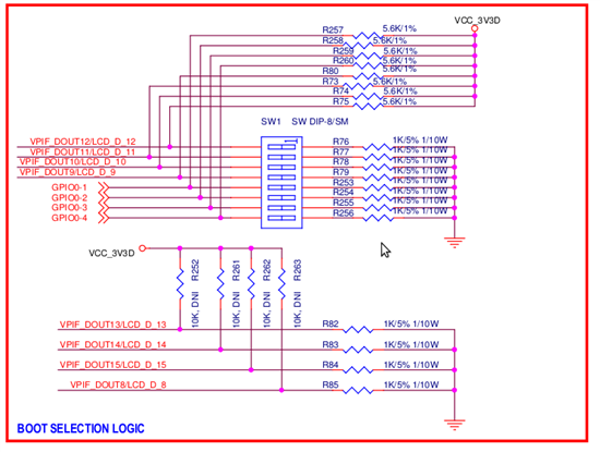
    Are you mentioning/referring the SW1 switch on LCDK board?

    If yes,

    S1,2,3,4 were used to boot mode pins

    S5,6,7,8 were mapped to GPIO1,2,3,4

    Please refer the C6748LCDK schematic.

  • Ok that it is mentionned in the shematic. Ok thank you.

    I will see the example to use switches of starterWare. I will download it.

    Wht do you think about the application : To remplace the facedetect function and replace it by the function flip and use switches.

    Tnaks and regards.

  • Hi,

    Wht do you think about the application : To remplace the facedetect function and replace it by the function flip and use switches.

    For this, You will get answer from our VPIF/Display experts soon.

  • Thank you very much

    Could you please give me the link to post on the forum TI of  VPIF/Display experts

    Thanks&Regards

    Mus An

  • Hi,

    Don't be worried.

    You will get support from this forum itself.

  • Hello !!

    I see the example but i didn't undestand many fuctions.

    The example given in gpio example is :

    #include "gpio.h"
    #include "psc.h"

    #include "soc_C6748.h"
    #include "lcdkC6748.h"

    /****************************************************************************/
    /* LOCAL FUNCTION PROTOTYPES */
    /****************************************************************************/
    static void Delay(volatile unsigned int delay);

    /****************************************************************************/
    /* GLOBAL VARIABLES */
    /****************************************************************************/

    /****************************************************************************/
    /* LOCAL FUNCTION DEFINITIONS */
    /****************************************************************************/

    int main(void)
    {


    /* The Local PSC number for GPIO is 3. GPIO belongs to PSC1 module.*/
    PSCModuleControl(SOC_PSC_1_REGS, HW_PSC_GPIO, PSC_POWERDOMAIN_ALWAYS_ON,
    PSC_MDCTL_NEXT_ENABLE);

    /* Pin Multiplexing of pin 12 of GPIO Bank 6.*/
    GPIOBank6Pin12PinMuxSetup();

    /* Sets the pin 109 (GP6[12]) as input.*/
    GPIODirModeSet(SOC_GPIO_0_REGS, 109, GPIO_DIR_OUTPUT);

    while(1)
    {
    GPIOPinWrite(SOC_GPIO_0_REGS, 109, GPIO_PIN_LOW);

    Delay(1000000);

    GPIOPinWrite(SOC_GPIO_0_REGS, 109, GPIO_PIN_HIGH);

    Delay(1000000);
    }


    }

    /*
    ** \brief This function checks the insertion status of the MMC/SD card
    ** in the device and prints related statements on the serial
    ** commuincation console of the external device.
    **
    */

    /*
    ** \brief This function can be called to generate a delay.
    */

    static void Delay(volatile unsigned int delay)
    {
    while(delay--);
    }


    /*****************************END OF FILE************************************/

    The Psc function is of configuring power and reste.

    Why do we use ths function GPIOBank6Pin12PinMuxSetup(); ?

    /* Sets the pin 109 (GP6[12]) as input.*/

    GPIODirModeSet(SOC_GPIO_0_REGS, 109, GPIO_DIR_OUTPUT);

    Why we make GPIO_DIR_OUTPUT to set GP6[12] as input, we need not use GPIO_DIR_INPUT ??

    Do you have a function to read the state of switches like GPIOPinRead ?

    I need to write a simple code to read the state of switches 

    Thanks & Regards

  • Is this code is correct :

    ***************************************************************************************************************************

    #include "gpio.h"
    #include "psc.h"

    #include "soc_C6748.h"
    #include "lcdkC6748.h"


    int main(void)
    {


    /* The Local PSC number for GPIO is 0. GPIO belongs to PSC1 module.*/
    PSCModuleControl(SOC_PSC_0_REGS, HW_PSC_GPIO, PSC_POWERDOMAIN_ALWAYS_ON,
    PSC_MDCTL_NEXT_ENABLE);

    /* Pin Multiplexing of pin 1-4 of GPIO Bank 0 to configure switches */
    GPIOBank0Pin1PinMuxSetup();
    GPIOBank0Pin2PinMuxSetup();
    GPIOBank0Pin3PinMuxSetup();
    GPIOBank0Pin4PinMuxSetup();

    /* Sets the pin 1 (GP0[1]), (GP0[2]),(GP0[3]) and (GP0[4]) as input.*/
    GPIODirModeSet(SOC_GPIO_0_REGS, 1, GPIO_DIR_INPUT);
    GPIODirModeSet(SOC_GPIO_0_REGS, 2, GPIO_DIR_INPUT);
    GPIODirModeSet(SOC_GPIO_0_REGS, 3, GPIO_DIR_INPUT);
    GPIODirModeSet(SOC_GPIO_0_REGS, 4, GPIO_DIR_INPUT);


    while(1)
    {
    if(OUT_DATA01=0x00000002) // to read the state of the switch 1
    {
    }
    if(OUT_DATA01=0x00000004) // to read the state of the switch 2
    {
    }
    if(OUT_DATA01=0x00000008) // to read the state of the switch 3
    {
    }
    if(OUT_DATA01=0x00000010) // to read the state of the switch 4
    {
    }


    }


    }

  • Hi,

    Why do we use ths function GPIOBank6Pin12PinMuxSetup(); ?

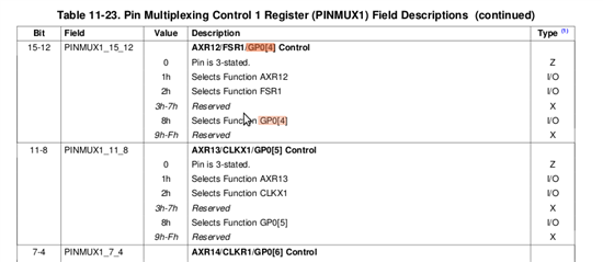
    In any ARM/DSP processor, the pin multiplexing  is used to perform multiple peripheral access on the same pin.

    This function is used to pinmux to GPIO access gp6[12] ie GPIO no 109

    The pinmux has been done through PINMUX registers.

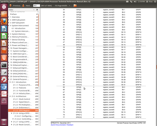
    Please refer the chapter 21.2.5 of OMAPL138 TRM

    Why we make GPIO_DIR_OUTPUT to set GP6[12] as input, we need not use GPIO_DIR_INPUT ??

    In General, The GPIO has to be 'set' or '1' if you wish to access the GPIO as input.

    The GPIO has to be 'clear' or '0' if you wish to access the GPIO as output.

    Do you have a function to read the state of switches like GPIOPinRead ?

    This "if (GPIOPinRead(SOC_GPIO_0_REGS, 65))" function is used to read the value of GP4[0] ie GPIO no 65

    For the code which you attached,

    The function seems to be Ok, but need to verify through emulator to read the content of every GPIO registers

    including PINMUX or at least try to print the content of registers.

    Do you have emulator with you?

    Try to debug your code by "step into" & "step over" options from CCS that whether the registers getting modified

    after the line executed.

  • Hello !!

    I would juste unsderstand the functions of the example, I didn't write it. and I use C6748 LCDK not OMAP

    I read the user's guide. and I see that to read  the state of the switch or any pin of banks GPIO we need to use 

    (INT_DATAn). I didn't found the GPIOPinRead in the documentation.

    Could you show me where you found it in the documentation of LCDK c6748

    for me to read the state of switch . I need to use this :

    #include "gpio.h"
    #include "psc.h"

    #include "soc_C6748.h"
    #include "lcdkC6748.h"


    int main(void)
    {


    /* The Local PSC number for GPIO is 0. GPIO belongs to PSC1 module.*/
    PSCModuleControl(SOC_PSC_0_REGS, HW_PSC_GPIO, PSC_POWERDOMAIN_ALWAYS_ON,
    PSC_MDCTL_NEXT_ENABLE);

    /* Sets the pin 1 (GP0[1]), (GP0[2]),(GP0[3]) and (GP0[4]) as input.*/
    GPIODirModeSet(SOC_GPIO_0_REGS, 1, GPIO_DIR_INPUT);
    GPIODirModeSet(SOC_GPIO_0_REGS, 2, GPIO_DIR_INPUT);
    GPIODirModeSet(SOC_GPIO_0_REGS, 3, GPIO_DIR_INPUT);
    GPIODirModeSet(SOC_GPIO_0_REGS, 4, GPIO_DIR_INPUT);


    while(1)
    {
    if(IN_DATA01=0x00000002) // to read the state of the switch 1
    {
    }
    if(IN_DATA01=0x00000004) // to read the state of the switch 2
    {
    }
    if(IN_DATA01=0x00000008) // to read the state of the switch 3
    {
    }
    if(IN_DATA01=0x00000010) // to read the state of the switch 4
    {
    }


    }


    }

  • Hi Mus,

    Could you please close this thread if you don't have a further questions and also we addressed all the queries related to switch(i/p) & LED (o/p) and provide examples of code too.

    http://e2e.ti.com/support/dsp/tms320c6000_high_performance_dsps/f/115/t/341382.aspx