Because of the Thanksgiving holiday in the U.S., TI E2E™ design support forum responses may be delayed from November 25 through December 2. Thank you for your patience.

This thread has been locked.

If you have a related question, please click the "Ask a related question" button in the top right corner. The newly created question will be automatically linked to this question.

help for my simple code/ Use of switches

Other Parts Discussed in Thread: OMAPL138

Hello !!

This is code that i wrote to read the state of switches. I would add it to the facedetect program :

/**
* \file switches.c
*
* \ this file is to call functions when the switches are selected
when the switch 1 is selected we call the horizontal flip function from the cxcore header file
when the switch 2 is selected we call the vertical flip function from the cxcore header file
when the switch 3 is selected we call the horizontal and the vertical function from the cxcore file
*/

#include "gpio.h"
#include "psc.h"

#include "soc_C6748.h"
#include "lcdkC6748.h"

/****************************************************************************/
/* LOCAL FUNCTION PROTOTYPES */
/****************************************************************************/
/****************************************************************************/
/* GLOBAL VARIABLES */
/****************************************************************************/
/****************************************************************************/
/* LOCAL FUNCTION DEFINITIONS */
/****************************************************************************/

int main(void)
{


/* The Local PSC number for GPIO is 3. GPIO belongs to PSC1 module.*/
PSCModuleControl(SOC_PSC_1_REGS, HW_PSC_GPIO, PSC_POWERDOMAIN_ALWAYS_ON, // I don't know how to modify this
PSC_MDCTL_NEXT_ENABLE);


/* Sets the pin 0,1,2,3 and for of GPIO0 as input.*/
GPIODirModeSet(SOC_GPIO_0_REGS, 1, GPIO_DIR_OUTPUT);
GPIODirModeSet(SOC_GPIO_0_REGS, 2, GPIO_DIR_OUTPUT);
GPIODirModeSet(SOC_GPIO_0_REGS, 3, GPIO_DIR_OUTPUT);


while(1)
{

int state_switch_1 =GPIOPinRead(unsigned int baseAdd, 1) // // to read the value of the pin 1 Bank 0
int state_switch_2 =GPIOPinRead(unsigned int baseAdd, 2) // // to read the value of the pin 1 Bank 0
int state_switch_3 =GPIOPinRead(unsigned int baseAdd, 3) // // to read the value of the pin 1 Bank 0
int state_switch_4 =GPIOPinRead(unsigned int baseAdd, 4) // // to read the value of the pin 1 Bank 0

if (state_switch_1==GPIO_PIN_HIGH)
{
// Call the horizontal flip function
}

else if(state_switch_2==GPIO_PIN_HIGH)
{
// call the vertical flip function
}
else (state_switch_3==GPIO_PIN_HIGH)
{
// call the horizontal an d the vertical flip function
}

}


}

It seem correct ?. I dont know how to get baseAdd of each pin.?

Regards

Mus

  • Hi Mustapha,

    I think that we clarified/discussed these same scenario/cases in many thread.

    http://e2e.ti.com/support/dsp/tms320c6000_high_performance_dsps/f/115/t/339304.aspx

    Still, Are you hanging on the same problem?

    Do you have emulator with you?

    Just, Do code walk through and understand the each and every line of code and ask us if you stuck with anything.

    I hope that we have added comments too for each & every line.

    Do not put plain question.

    Also We referred the gpio examples,

    Firstly, Try to build & debug the actual TI examples of GPIO.

    Secondly, Modify the codes as per your requirement with debugging.

    If you continuing in creating multiple threads then sorry to say that your questions may leads to unanswered unless you didn't follow our suggestions & steps.

    Thanks for your understanding.

    Good luck for your developments.

  • Hi Anouini,

    Anouini says said:
    It seem correct ?. I dont know how to get baseAdd of each pin.?

    Please go through the GPIO sections in the Data sheet and TRM of C6748; you will get all the necessary details like byte address of GPIO registers e.t.c.,

    http://www.ti.com/product/tms320c6748


    Regards,

    Shankari

  • Thank you !!

    I will see that 

    Mus

  • Hi,

    1) You missed to pinmux for GPIO which you are going to access the flip fns.

    Ex;

    /* Pin Multiplexing of pin 12 of GPIO Bank 6.*/
        GPIOBank6Pin12PinMuxSetup();

    2) The GPIO base address is "0x01E26000" and you can also use this macro "SOC_GPIO_0_REGS"

    ex;

    int state_switch_1 =GPIOPinRead(SOC_GPIO_0_REGS, 1) // // to read the value of the pin 1 Bank 0

    What do you say?

    Also, I have started to write starterware GPIO code for your requirement in C6748 LCDK board and Will update once i done.

  • Hi,

    This is code for GPIO switch function from C6748 LCDK board.

    Compile the "gpio_flip.c" file and try to load & test with S3 (User 2) switch on C6748 LCDK board.

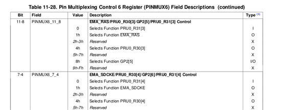
    S3 switch is mapped to GPIO2[5] which is from PINMUX6 register and its gpio no is 38

    Please refer the C6748 TRM and attachments.

    /**
    * \file    gpio_flip.c
    *
    * \brief   This is a sample application file demonstrating the use of
    *          a GPIO pin for input
    *
    *
    * Copyright (C) 2012 Texas Instruments Incorporated - http://www.ti.com/  
    *
    *  Redistribution and use in source and binary forms, with or without  
    *  modification, are permitted provided that the following conditions  
    *  are met:
    *
    *    Redistributions of source code must retain the above copyright  
    *    notice, this list of conditions and the following disclaimer.
    *
    *    Redistributions in binary form must reproduce the above copyright
    *    notice, this list of conditions and the following disclaimer in the  
    *    documentation and/or other materials provided with the    
    *    distribution.
    *
    *    Neither the name of Texas Instruments Incorporated nor the names of
    *    its contributors may be used to endorse or promote products derived
    *    from this software without specific prior written permission.
    *
    *  THIS SOFTWARE IS PROVIDED BY THE COPYRIGHT HOLDERS AND CONTRIBUTORS  
    *  "AS IS" AND ANY EXPRESS OR IMPLIED WARRANTIES, INCLUDING, BUT NOT  
    *  LIMITED TO, THE IMPLIED WARRANTIES OF MERCHANTABILITY AND FITNESS FOR
    *  A PARTICULAR PURPOSE ARE DISCLAIMED. IN NO EVENT SHALL THE COPYRIGHT  
    *  OWNER OR CONTRIBUTORS BE LIABLE FOR ANY DIRECT, INDIRECT, INCIDENTAL,  
    *  SPECIAL, EXEMPLARY, OR CONSEQUENTIAL DAMAGES (INCLUDING, BUT NOT  
    *  LIMITED TO, PROCUREMENT OF SUBSTITUTE GOODS OR SERVICES; LOSS OF USE,
    *  DATA, OR PROFITS; OR BUSINESS INTERRUPTION) HOWEVER CAUSED AND ON ANY
    *  THEORY OF LIABILITY, WHETHER IN CONTRACT, STRICT LIABILITY, OR TORT  
    *  (INCLUDING NEGLIGENCE OR OTHERWISE) ARISING IN ANY WAY OUT OF THE USE  
    *  OF THIS SOFTWARE, EVEN IF ADVISED OF THE POSSIBILITY OF SUCH DAMAGE.
    */
     
    #include<stdio.h>
     
    #include "gpio.h"
    #include "psc.h"
     
    #include "soc_OMAPL138.h"
    #include "lcdkOMAPL138.h"
     
    /* HW Macros */
    #include "hw_types.h"
     
    /* System Defines */
    #include "lcdkOMAPL138.h"
    #include "soc_OMAPL138.h"
    #include "hw_syscfg0_OMAPL138.h"


    /* Titus : GP2[5] is mapped to switch S3 on OMAPL138/C6748 LCDK boards */
     
    /* Pin Multiplexing bit mask to select GP2[5] pin. */
    #define PINMUX6_GPIO2_5_ENABLE    (SYSCFG_PINMUX6_PINMUX6_11_8_GPIO2_5  << \
                                        SYSCFG_PINMUX6_PINMUX6_11_8_SHIFT)
     
     
    /* Titus : GP2[5] is mapped to switch S3 on OMAPL138/C6748 LCDK boards */
     
        /* Pin Multiplexing of pin 5 of GPIO Bank 2.*/


    void GPIOBank2Pin5PinMuxSetup(void)
    {
         unsigned int savePinmux = 0;
     
         /*
         ** Clearing the bit in context and retaining the other bit values
         ** in PINMUX6 register.
         */
         savePinmux = (HWREG(SOC_SYSCFG_0_REGS + SYSCFG0_PINMUX(6)) &
                      ~(SYSCFG_PINMUX6_PINMUX6_11_8));
     
         /* Setting the pins corresponding to GP2[5] in PINMUX6 register.*/
         HWREG(SOC_SYSCFG_0_REGS + SYSCFG0_PINMUX(6)) =
              (PINMUX6_GPIO2_5_ENABLE | savePinmux);
     
    }
     
     
    int main(void)
    {
     
     
        /* The Local PSC number for GPIO is 3. GPIO belongs to PSC1 module.*/
        PSCModuleControl(SOC_PSC_1_REGS, HW_PSC_GPIO, PSC_POWERDOMAIN_ALWAYS_ON,
                 PSC_MDCTL_NEXT_ENABLE);
     
     
        /* Titus : GP2[5] is mapped to switch S3 on OMAPL138/C6748 LCDK boards */
     
        /* Pin Multiplexing of pin 5 of GPIO Bank 2.*/
        GPIOBank2Pin5PinMuxSetup();
     
        /* Sets the pin 109 (GP2[5]) as input.*/
     
        /* Titus : 38 is the GPIO no for GP2[5]; Refer page no 901 in OMAPL138/C6748 TRM */
     
        GPIODirModeSet(SOC_GPIO_0_REGS, 38, GPIO_DIR_INPUT);
     
        while(1)
        {
     
        /* Titus : 38 is the GPIO no for GP2[5]; Refer page no 901 in OMAPL138/C6748 TRM */
     
            if (GPIOPinRead(SOC_GPIO_0_REGS, 38))
            {
                printf("Switch S3 is not pressed\n");
            }
            else
            {
                printf("Switch S3 is pressed\n");
     
            }
     
        }
     
     
    } 


    I hope this helps.

  • Hello !!

    I use the LCDK C 6748. I think i would be te same logic of code with some différences. 

    Thank you very much

    Mus An

  • Hi,

    You can use this code for OMAPL138 LCDK and C6748 LCDK board too

    You need to mention target type (C6000 or ARM) while creating CCS project.

    FYI,

    I have tested this code on C6748 LCDK only.

    You can post your queries in this thread if any doubts on this code.

    Good luck.

  • Hi Mus,

    Do you have any doubt on this thread?

    If not, Could you please close the thread.

  • Hello !!

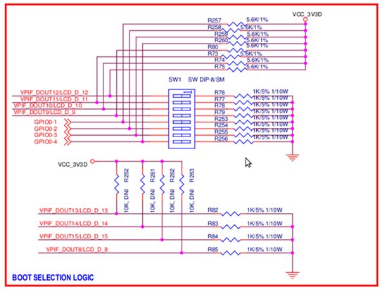
    The code is work but i didn't understand.In the shématic The switches 1,2,3,4 is mapped to GPIO0[1],GPIO0[2],GPIO0[3] and GPIO0[4].

    Why S3 is mapped to GP2[5]. Where did you found this?

    In the example given by TI. To set a pin as input. They use

      /* Sets the pin 109 (GP6[12]) as input.*/
        GPIODirModeSet(SOC_GPIO_0_REGS, 109, GPIO_DIR_OUTPUT);

    /**
     * \file    gpioCardDetect.c
     *
     * \brief   This is a sample application file demonstrating the use of
     *          a GPIO pin to generate an interrupt whenever an MMC/SD card
     *          is inserted or ejected from the Evaluation Module(EVM).
     */

    /*
    * Copyright (C) 2012 Texas Instruments Incorporated - http://www.ti.com/
    *
    *  Redistribution and use in source and binary forms, with or without
    *  modification, are permitted provided that the following conditions
    *  are met:
    *
    *    Redistributions of source code must retain the above copyright
    *    notice, this list of conditions and the following disclaimer.
    *
    *    Redistributions in binary form must reproduce the above copyright
    *    notice, this list of conditions and the following disclaimer in the
    *    documentation and/or other materials provided with the   
    *    distribution.
    *
    *    Neither the name of Texas Instruments Incorporated nor the names of
    *    its contributors may be used to endorse or promote products derived
    *    from this software without specific prior written permission.
    *
    *  THIS SOFTWARE IS PROVIDED BY THE COPYRIGHT HOLDERS AND CONTRIBUTORS
    *  "AS IS" AND ANY EXPRESS OR IMPLIED WARRANTIES, INCLUDING, BUT NOT
    *  LIMITED TO, THE IMPLIED WARRANTIES OF MERCHANTABILITY AND FITNESS FOR
    *  A PARTICULAR PURPOSE ARE DISCLAIMED. IN NO EVENT SHALL THE COPYRIGHT
    *  OWNER OR CONTRIBUTORS BE LIABLE FOR ANY DIRECT, INDIRECT, INCIDENTAL,
    *  SPECIAL, EXEMPLARY, OR CONSEQUENTIAL DAMAGES (INCLUDING, BUT NOT
    *  LIMITED TO, PROCUREMENT OF SUBSTITUTE GOODS OR SERVICES; LOSS OF USE,
    *  DATA, OR PROFITS; OR BUSINESS INTERRUPTION) HOWEVER CAUSED AND ON ANY
    *  THEORY OF LIABILITY, WHETHER IN CONTRACT, STRICT LIABILITY, OR TORT
    *  (INCLUDING NEGLIGENCE OR OTHERWISE) ARISING IN ANY WAY OUT OF THE USE
    *  OF THIS SOFTWARE, EVEN IF ADVISED OF THE POSSIBILITY OF SUCH DAMAGE.
    */

    #include "gpio.h"
    #include "psc.h"

    #include "soc_C6748.h"
    #include "lcdkC6748.h"

    /****************************************************************************/
    /*              LOCAL FUNCTION PROTOTYPES                                   */
    /****************************************************************************/
    static void Delay(volatile unsigned int delay);

    /****************************************************************************/
    /*              GLOBAL VARIABLES                                            */
    /****************************************************************************/

    /****************************************************************************/
    /*             LOCAL FUNCTION DEFINITIONS                                   */
    /****************************************************************************/

    int main(void)
    {


        /* The Local PSC number for GPIO is 3. GPIO belongs to PSC1 module.*/
        PSCModuleControl(SOC_PSC_1_REGS, HW_PSC_GPIO, PSC_POWERDOMAIN_ALWAYS_ON,
                 PSC_MDCTL_NEXT_ENABLE);

        /* Pin Multiplexing of pin 12 of GPIO Bank 6.*/
        GPIOBank6Pin12PinMuxSetup();

        /* Sets the pin 109 (GP6[12]) as input.*/
        GPIODirModeSet(SOC_GPIO_0_REGS, 109, GPIO_DIR_OUTPUT);

        while(1)
        {
            GPIOPinWrite(SOC_GPIO_0_REGS, 109, GPIO_PIN_LOW);

            Delay(1000000);

            GPIOPinWrite(SOC_GPIO_0_REGS, 109, GPIO_PIN_HIGH);

            Delay(1000000);
        }


    }

    /*
    ** \brief  This function checks the insertion status of the MMC/SD card
    **         in the device and prints related statements on the serial
    **         commuincation console of the external device.
    **         
    */

    /*
    ** \brief   This function can be called to generate a delay.
    */

    static void Delay(volatile unsigned int delay)
    {
        while(delay--);
    }


    /*****************************END OF FILE************************************/

    The last question. Why do you set up GPIOBank2Pin5PinMux.

    I have a doubt of a lot of thing. For me the code that should work is this :

    In the descxription of the function on GPIO.c

    /**
     * \brief  This function gets the direction of a pin which has been configured
     *         as an input or an output pin.
     *
     * \param   baseAdd    The memory address of the GPIO instance being used.
     * \param   pinNumber  The serial number of the GPIO pin.
     *                     The 144 GPIO pins have serial numbers from 1 to 144.                      
     *
     * \return  This returns one of the following two values:
     *          1> GPIO_DIR_INPUT, if the pin is configured as an input pin.
     *          2> GPIO_DIR_OUTPUT, if the pin is configured as an output pin.
     *

    The code given by Texas in the examples is wrong?

    Thank you !!

  • Hi Mus,

    Why do you set up GPIOBank2Pin5PinMux.

        /* Titus : GP2[5] is mapped to switch S3 on OMAPL138/C6748 LCDK boards */
     
        /* Pin Multiplexing of pin 5 of GPIO Bank 2.*/
        GPIOBank2Pin5PinMuxSetup();
    In code comment itself given clearly that switch S3 is mapped to GPIO2[5] as per the LCDK schematics.
    Still, You have problem on understanding !
    Please refer the LCDK schematics page no 4.

    To set a pin as input. They use

      /* Sets the pin 109 (GP6[12]) as input.*/
        GPIODirModeSet(SOC_GPIO_0_REGS, 109, GPIO_DIR_OUTPUT);

    Oh !

    I got your doubt now,

    Sorry, It might be problem in commenting.

    It would be "OUTPUT" only,

    If they set to OUTPUT then why the code had set to LOW and HIGH in while loop.

    Understood my point !
    In that way only I had set to INPUT in my code.
       /* Sets the pin 109 (GP6[12]) as input. Titus :"it is output" */
        GPIODirModeSet(SOC_GPIO_0_REGS, 109, GPIO_DIR_OUTPUT);

        while(1)
        {
            GPIOPinWrite(SOC_GPIO_0_REGS, 109, GPIO_PIN_LOW);

            Delay(1000000);

            GPIOPinWrite(SOC_GPIO_0_REGS, 109, GPIO_PIN_HIGH);

            Delay(1000000);
        }
  • Ok for the GPIO number. Thank you.

    But why you have GPIO0-1 , GPIO0-2,GPIO0-3,GPIO0-4 for S1,S2,S3 and S4. And in the some document w have

    GPIO2-4 and GPIO2-5 for S2 and S3 in the some documents ?

    Is this my doubt?


    Thank you very much

  • Hi,

    But why you have GPIO0-1 , GPIO0-2,GPIO0-3,GPIO0-4 for S1,S2,S3 and S4. And in the some document w have

    There is difference between S3 and SW1[3]

    Switch 'S3' is push button switch in LCDK which I mentioning in code

    SW1[3] is DIP switch.

    Why output. To set switches as input we need to use input as defined in the GPIO deriver.?

    I told you clearly that there was a error in the commented text in the TI code of GPIO.

    Please read my answers clearly since I'm spending much time to type all those suggestions/testing/coding,

    If you want to make a GPIO as o/p then it could be OUTPUT only.

    What you have to do with GP0[1], GP0[2] etc. ?

    input or output ?

  • i see is this the confusion we have 3 push button and 8 switches.

    I need to use the push button or switch to call functions for openCV.

    If the push button is set then i call a function else if push button 2 is set i call another. The function that i would call is the flip function inc Cxcore.h.

    Excuse me I didn't read clearly your response. Now All thing is clear.


    Thank you

  • Hi,

    The following code will demonstrate the GPIOs as input and output on OMAPL138/C6748 LCDK board..

    The DIP switch (SW1) will control the LEDs.

    When you switch ON the any one of the DIP switch (other than boot switch) from 5,6,7,8 then corresponding LED will glow.

    Switches -> DIP switch Sw1[5:8]

    LEDs -> D4,D5,D6,D7

    /**
    * \file    gpio_flip.c
    *
    * \brief   This is a sample application file demonstrating the use of
    *          a GPIO pin for input (DIP switch) and output (LED)
    *
    *
    * Copyright (C) 2012 Texas Instruments Incorporated - http://www.ti.com/ 
    *
    *  Redistribution and use in source and binary forms, with or without 
    *  modification, are permitted provided that the following conditions 
    *  are met:
    *
    *    Redistributions of source code must retain the above copyright 
    *    notice, this list of conditions and the following disclaimer.
    *
    *    Redistributions in binary form must reproduce the above copyright
    *    notice, this list of conditions and the following disclaimer in the 
    *    documentation and/or other materials provided with the   
    *    distribution.
    *
    *    Neither the name of Texas Instruments Incorporated nor the names of
    *    its contributors may be used to endorse or promote products derived
    *    from this software without specific prior written permission.
    *
    *  THIS SOFTWARE IS PROVIDED BY THE COPYRIGHT HOLDERS AND CONTRIBUTORS 
    *  "AS IS" AND ANY EXPRESS OR IMPLIED WARRANTIES, INCLUDING, BUT NOT 
    *  LIMITED TO, THE IMPLIED WARRANTIES OF MERCHANTABILITY AND FITNESS FOR
    *  A PARTICULAR PURPOSE ARE DISCLAIMED. IN NO EVENT SHALL THE COPYRIGHT 
    *  OWNER OR CONTRIBUTORS BE LIABLE FOR ANY DIRECT, INDIRECT, INCIDENTAL, 
    *  SPECIAL, EXEMPLARY, OR CONSEQUENTIAL DAMAGES (INCLUDING, BUT NOT 
    *  LIMITED TO, PROCUREMENT OF SUBSTITUTE GOODS OR SERVICES; LOSS OF USE,
    *  DATA, OR PROFITS; OR BUSINESS INTERRUPTION) HOWEVER CAUSED AND ON ANY
    *  THEORY OF LIABILITY, WHETHER IN CONTRACT, STRICT LIABILITY, OR TORT 
    *  (INCLUDING NEGLIGENCE OR OTHERWISE) ARISING IN ANY WAY OUT OF THE USE 
    *  OF THIS SOFTWARE, EVEN IF ADVISED OF THE POSSIBILITY OF SUCH DAMAGE.
    */
    
    #include<stdio.h>
    
    #include "gpio.h"
    #include "psc.h"
    
    #include "soc_OMAPL138.h"
    #include "lcdkOMAPL138.h"
    
    /* HW Macros */
    #include "hw_types.h"
    
    /* System Defines */
    #include "lcdkOMAPL138.h"
    #include "soc_OMAPL138.h"
    #include "hw_syscfg0_OMAPL138.h"


    /* Switch Configuration */
    
    /* Titus : GP0[1] to GP0[4] is mapped to SW1[3:4] on OMAPL138/C6748 LCDK boards */
    
    /* Pin Multiplexing bit mask to select GP0[1] to GP0[4] pin. */
    
    #define PINMUX1_GPIO0_1_ENABLE    (SYSCFG_PINMUX1_PINMUX1_27_24_GPIO0_1  << \
                                        SYSCFG_PINMUX1_PINMUX1_27_24_SHIFT)
    
    #define PINMUX1_GPIO0_2_ENABLE    (SYSCFG_PINMUX1_PINMUX1_23_20_GPIO0_2  << \
                                        SYSCFG_PINMUX1_PINMUX1_23_20_SHIFT)
    
    #define PINMUX1_GPIO0_3_ENABLE    (SYSCFG_PINMUX1_PINMUX1_19_16_GPIO0_3  << \
                                        SYSCFG_PINMUX1_PINMUX1_19_16_SHIFT)
    
    #define PINMUX1_GPIO0_4_ENABLE    (SYSCFG_PINMUX1_PINMUX1_15_12_GPIO0_4  << \
                                        SYSCFG_PINMUX1_PINMUX1_15_12_SHIFT)
    
    
    /* LED Configuration */
    
    /* Titus : GP6[12], GP6[13], GP2[12] and GP0[9] is mapped to D4, D5, D6, D7 LEDs on OMAPL138/C6748 LCDK boards */
    
    /* Pin Multiplexing bit mask to select GP6[12] pin. */
    #define PINMUX13_GPIO6_12_ENABLE    (SYSCFG_PINMUX13_PINMUX13_15_12_GPIO6_12  << \
                                        SYSCFG_PINMUX13_PINMUX13_15_12_SHIFT)
    
    /* Pin Multiplexing bit mask to select GP6[13] pin. */
    #define PINMUX13_GPIO6_13_ENABLE    (SYSCFG_PINMUX13_PINMUX13_11_8_GPIO6_13  << \
                                        SYSCFG_PINMUX13_PINMUX13_11_8_SHIFT)
    
    /* Pin Multiplexing bit mask to select GP2[12] pin. */
    #define PINMUX5_GPIO2_12_ENABLE    (SYSCFG_PINMUX5_PINMUX5_15_12_GPIO2_12  << \
                                        SYSCFG_PINMUX5_PINMUX5_15_12_SHIFT)
    
    /* Pin Multiplexing bit mask to select GP0[9] pin. */
    #define PINMUX0_GPIO0_9_ENABLE    (SYSCFG_PINMUX0_PINMUX0_27_24_GPIO0_9  << \
                                        SYSCFG_PINMUX0_PINMUX0_27_24_SHIFT)
    
    
    void PinMuxSetup_leds(void)
    {
         unsigned int savePinmux = 0;
    
    
         /*
         ** Clearing the bit in context and retaining the other bit values
         ** in PINMUX13 register.
         */
         savePinmux = (HWREG(SOC_SYSCFG_0_REGS + SYSCFG0_PINMUX(13)) &
                      ~(SYSCFG_PINMUX13_PINMUX13_15_12));
    
         /* Setting the pins corresponding to GP6[12] in PINMUX13 register.*/
         HWREG(SOC_SYSCFG_0_REGS + SYSCFG0_PINMUX(13)) =
              (PINMUX13_GPIO6_12_ENABLE | savePinmux);
    
    
         /*
         ** Clearing the bit in context and retaining the other bit values
         ** in PINMUX13 register.
         */
         savePinmux = (HWREG(SOC_SYSCFG_0_REGS + SYSCFG0_PINMUX(13)) &
                      ~(SYSCFG_PINMUX13_PINMUX13_11_8));
    
         /* Setting the pins corresponding to GP6[13] in PINMUX13 register.*/
         HWREG(SOC_SYSCFG_0_REGS + SYSCFG0_PINMUX(13)) =
              (PINMUX13_GPIO6_13_ENABLE | savePinmux);
    
    
         /*
         ** Clearing the bit in context and retaining the other bit values
         ** in PINMUX5 register.
         */
         savePinmux = (HWREG(SOC_SYSCFG_0_REGS + SYSCFG0_PINMUX(5)) &
                      ~(SYSCFG_PINMUX5_PINMUX5_15_12));
    
         /* Setting the pins corresponding to GP2[12] in PINMUX5 register.*/
         HWREG(SOC_SYSCFG_0_REGS + SYSCFG0_PINMUX(5)) =
              (PINMUX5_GPIO2_12_ENABLE | savePinmux);
    
    
         /*
         ** Clearing the bit in context and retaining the other bit values
         ** in PINMUX0 register.
         */
         savePinmux = (HWREG(SOC_SYSCFG_0_REGS + SYSCFG0_PINMUX(0)) &
                      ~(SYSCFG_PINMUX0_PINMUX0_27_24));
    
         /* Setting the pins corresponding to GP0[9] in PINMUX0 register.*/
         HWREG(SOC_SYSCFG_0_REGS + SYSCFG0_PINMUX(0)) =
              (PINMUX0_GPIO0_9_ENABLE | savePinmux);
    
    }


    void PinMuxSetup_switches(void)
    {
         unsigned int savePinmux = 0;
    
         /* Setting the pins corresponding to GP0[1] in PINMUX1 register.*/
    
         /*
         ** Clearing the bit in context and retaining the other bit values
         ** in PINMUX1 register.
         */
         savePinmux = (HWREG(SOC_SYSCFG_0_REGS + SYSCFG0_PINMUX(1)) &
                      ~(SYSCFG_PINMUX1_PINMUX1_27_24));
    
    
         HWREG(SOC_SYSCFG_0_REGS + SYSCFG0_PINMUX(1)) =
              (PINMUX1_GPIO0_1_ENABLE | savePinmux);


         /* Setting the pins corresponding to GP0[2] in PINMUX1 register.*/
    
              /*
              ** Clearing the bit in context and retaining the other bit values
              ** in PINMUX1 register.
              */
              savePinmux = (HWREG(SOC_SYSCFG_0_REGS + SYSCFG0_PINMUX(1)) &
                           ~(SYSCFG_PINMUX1_PINMUX1_23_20));
    
    
              HWREG(SOC_SYSCFG_0_REGS + SYSCFG0_PINMUX(1)) =
                   (PINMUX1_GPIO0_2_ENABLE | savePinmux);


              /* Setting the pins corresponding to GP0[3] in PINMUX1 register.*/
    
                   /*
                   ** Clearing the bit in context and retaining the other bit values
                   ** in PINMUX1 register.
                   */
                   savePinmux = (HWREG(SOC_SYSCFG_0_REGS + SYSCFG0_PINMUX(1)) &
                                ~(SYSCFG_PINMUX1_PINMUX1_19_16));
    
    
                   HWREG(SOC_SYSCFG_0_REGS + SYSCFG0_PINMUX(1)) =
                        (PINMUX1_GPIO0_3_ENABLE | savePinmux);


                   /* Setting the pins corresponding to GP0[4] in PINMUX1 register.*/
    
                        /*
                        ** Clearing the bit in context and retaining the other bit values
                        ** in PINMUX1 register.
                        */
                        savePinmux = (HWREG(SOC_SYSCFG_0_REGS + SYSCFG0_PINMUX(1)) &
                                     ~(SYSCFG_PINMUX1_PINMUX1_15_12));
    
    
                        HWREG(SOC_SYSCFG_0_REGS + SYSCFG0_PINMUX(1)) =
                             (PINMUX1_GPIO0_4_ENABLE | savePinmux);
    
    
    }
    
    
    int main(void)
    {
    
    
        /* The Local PSC number for GPIO is 3. GPIO belongs to PSC1 module.*/
        PSCModuleControl(SOC_PSC_1_REGS, HW_PSC_GPIO, PSC_POWERDOMAIN_ALWAYS_ON,
    		     PSC_MDCTL_NEXT_ENABLE);
    
    
        /* Pin Multiplexing of pins GP0[1] to GP0[4] of GPIO Bank 2 for DIP SWITCHEs in OMAPL138 LCDK board */
        PinMuxSetup_switches();
    
        /* Pin Multiplexing of pins GP6[12], GP6[13], GP2[12], GP0[9], for LEDs in OMAPL138 LCDK board */
        PinMuxSetup_leds();
    
    
        /* Titus : 2,3,4,5 is the GPIO no for GP0[1] to GP0[4]; Refer page no 901 in OMAPL138/C6748 TRM */
    
    
    /* SWITCHEs SETUP */
    
        /* Sets the pin 2 (GP0[1]) as input.*/
        GPIODirModeSet(SOC_GPIO_0_REGS, 2, GPIO_DIR_INPUT);
    
        /* Sets the pin 3 (GP0[2]) as input.*/
        GPIODirModeSet(SOC_GPIO_0_REGS, 3, GPIO_DIR_INPUT);
    
        /* Sets the pin 4 (GP0[3]) as input.*/
        GPIODirModeSet(SOC_GPIO_0_REGS, 4, GPIO_DIR_INPUT);
    
        /* Sets the pin 5 (GP0[4]) as input.*/
        GPIODirModeSet(SOC_GPIO_0_REGS, 5, GPIO_DIR_INPUT);
    
    /* LEDs SETUP */
    
        /* Sets the pin 109 (GP6[12]) as output.*/
        GPIODirModeSet(SOC_GPIO_0_REGS, 109, GPIO_DIR_OUTPUT);
    
        /* Sets the pin 110 (GP6[13]) as output.*/
        GPIODirModeSet(SOC_GPIO_0_REGS, 110, GPIO_DIR_OUTPUT);
    
        /* Sets the pin 45 (GP2[12]) as output.*/
        GPIODirModeSet(SOC_GPIO_0_REGS, 45, GPIO_DIR_OUTPUT);
    
        /* Sets the pin 10 (GP0[9]) as output.*/
        GPIODirModeSet(SOC_GPIO_0_REGS, 10, GPIO_DIR_OUTPUT);
    
    
        while(1)
        {
    
        /* Titus : 2,3,4,5 is the GPIO no for GP0[1] to GP0[4]; Refer page no 901 in OMAPL138/C6748 TRM */
    
    	    if (GPIOPinRead(SOC_GPIO_0_REGS, 2))
    		{
    
    		GPIOPinWrite(SOC_GPIO_0_REGS, 109, GPIO_PIN_LOW);
        	printf("S1 is not pressed\n");
    
    		}
    
    	    else
    	    {

    //TODO
    /* Hi Mus: Put your flip code here for 90' */
    printf("S1 is pressed\n"); GPIOPinWrite(SOC_GPIO_0_REGS, 109, GPIO_PIN_HIGH); } if (GPIOPinRead(SOC_GPIO_0_REGS, 3)) { GPIOPinWrite(SOC_GPIO_0_REGS, 110, GPIO_PIN_LOW); printf("S2 is not pressed\n"); } else {
    //TODO
    /* Hi Mus: Put your flip code here for 180' */
    printf("S2 is pressed\n"); GPIOPinWrite(SOC_GPIO_0_REGS, 110, GPIO_PIN_HIGH); } if (GPIOPinRead(SOC_GPIO_0_REGS, 4)) { GPIOPinWrite(SOC_GPIO_0_REGS, 45, GPIO_PIN_LOW); printf("S3 is not pressed\n"); } else {
    //TODO
    /* Hi Mus: Put your flip code here for 270' */
    printf("S3 is pressed\n"); GPIOPinWrite(SOC_GPIO_0_REGS, 45, GPIO_PIN_HIGH); } if (GPIOPinRead(SOC_GPIO_0_REGS, 5)) { GPIOPinWrite(SOC_GPIO_0_REGS, 10, GPIO_PIN_LOW); printf("S4 is not pressed\n"); } else {
    //TODO
    /* Hi Mus: Put your flip code here for 0' or 360'' */
    printf("S4 is pressed\n"); GPIOPinWrite(SOC_GPIO_0_REGS, 10, GPIO_PIN_HIGH); } } }
  • Hello !!

    Thank you very much for the code. It still clear now how to use GPIO.  But I don't know how we use the pinmux and how to Clear the bit in context and retaining the other bit value.

    This part of code is not clear.

    How does one configure the PINMUX registers on a C6748 DSP? I didn't found i document of texas instrument for this

    Thank you

  • Hi,

    How does one configure the PINMUX registers on a C6748 DSP? I didn't found i document of texas instrument for this

    Please refer the C6748 TRM for PINMUX registers.

    What is PINMUX, Why PINMUX, etc.,

  • Hello !!

    I found some pdf from texas but they give a smal definition. Can you give me the link that explain PINMUX register on details.

    Thank you !!

    Mus

  • Hi Anouini Mustapha,

    Anouini says said:
    Can you give me the link that explain PINMUX register on details.

    There is a pinmux utility released by TI. That utility  has a user interface and contains peripheral selection boxes where a group of pins are needed for the peripheral to operate.

    http://www.ti.com/lit/an/sprab63b/sprab63b.pdf

    In a literal meaning, Pinmultiplexing means "reusing the same pin for different purposes" by configuring them appropriately. PINMUX registers are set of registers which can control PINS.


    Regards,

    Shankari

    -------------------------------------------------------------------------------------------------------

    Please click the Verify Answer button on this post if it answers your question.
    --------------------------------------------------------------------------------------------------------

  • Ok I will see that in details.

    Thank you !!

  • Hello !!

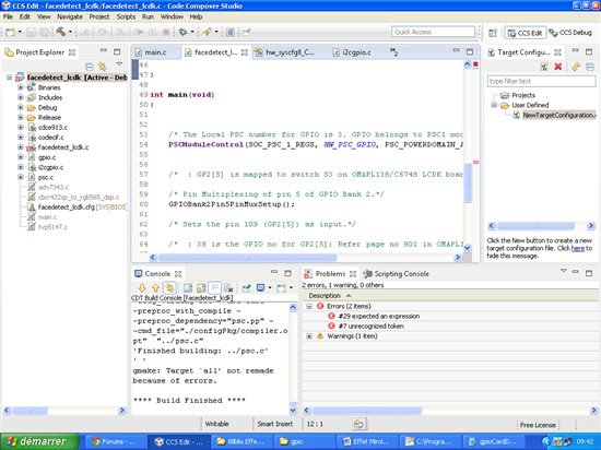
    Think you for your help I tested the flip program but i get 2 erros as shown in the picture bellow :

     *

    At this line :

    HWREG(SOC_SYSCFG_0_REGS + SYSCFG0_PINMUX(6)) =(PINMUX6_GPIO2_5_ENABLE|savePinmux);

    For the program of dip switchs i have no errors but i get no messages in the consolewhen a dip switch is selected

    Thaink you very much 

  • Hi,

    Why did you attach the library "psc.c" file into your project ?

    Just you can link the starterware libraries into your facedetect project to use PSC related APIs.

    Ex:

    drivers and system_config

  • Think you very much !!

    I attached just psc.c and gpio.c file in the c files. 

    How I  can link the starterware libraries into your facedetect project to use PSC related APIs.

    Could you show me how to do this in code composer studio V6 I'm biginner in CCS6

    Could you attach please the project that work for this.

    Think you

  • Hi,

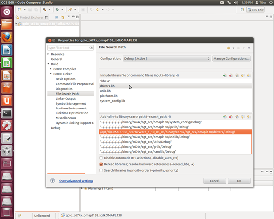
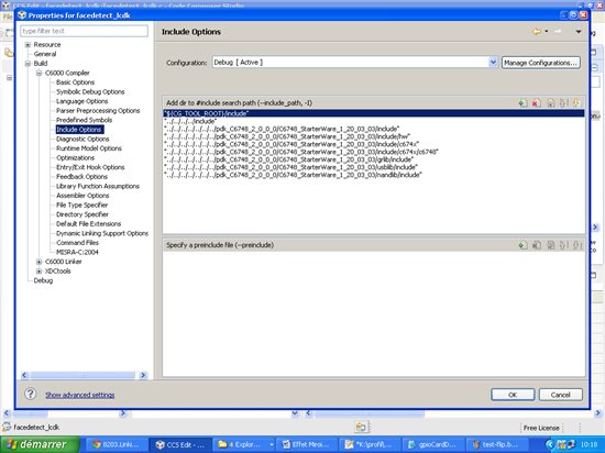
    Select the properties of "facedetect" project and link it as like attached screen shot.

  • I have this :

    It Ok i think ??

  • Hi,

    You have to change in "C6000 Linker" menu and not in "C6000 compiler" option.

    Please check my screens shot carefully.

  • It Work think you for your help !!