This thread has been locked.

If you have a related question, please click the "Ask a related question" button in the top right corner. The newly created question will be automatically linked to this question.

TPS25750: TPS25750 source as a device

Part Number: TPS25750

Hi,

I am using the TPS25750S on one of my design with the following goals (for my device):

- Act as a device in the USB data transmission

- Act as a source for power

- Use USB-C

The goal is to charge a USB-C Samsung tablet, while the latter handles the communications.

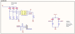
My design integrates the same EEPROM model as the EVM (evaluation module) and the I2C lines are exposed so I am able to use a flasher to push the binary generated with TI online GUI.

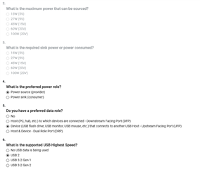
For the configuration, I am using the following parameters:

- Provider only (5V, 3A)

- Preferred role: power source

- Preferred data role: device

- Max data speed: USB2.0

- No product or vendor ID

When I am using this configuration, flashed on the EEPROM, my device works, except for the sourcing power part. The tablet always detects my device as a sink and Android displays a "USB supplying power to attached device" message.

I checked the CC lines during plug in operation, communication is happening.

I would like to get some help on this matter, maybe someone has already completed such a design with the TPS25750S ?

Thanks in advance for your help !

Best regards

  • You will have to change the configuration to the sink only option in the GUI.  It will be the lower left block in the GUI as shown below.

    You will also need to change the preferred data role to ensure that it is a source in your configuration.

    If you save off this binary, then you will power up the TPS25750 as a 5V source only on your board.

  • Hi Chuck,

    Thanks for the prompt reply !

    May I ask why I should use the lower left block (power SOURCE only) as opposed to the lower right one ?

    They do the same but I am using a TPS25750S and not a TPS25750D.

    Best regards,

    Marc

    EDIT: this did not solve the issue

    Here is a screenshot of the configuration (below the architecture block selection in the GUI)

  • Marc,

    My error.  You should use the 25750S configuration for the TPS25750S part.

    The rest of your GUI configuration looks correct.

    Are you providing PP5V and VIN_3V3 to the device?

    Are you able to share just the section of your schematic around the TPS25750S so that I can check the connections?

  • Hello Chuck,

    Yes I can provide some schematics elements.
    Here is the TPS25750S 


    Here is VBUS and 5V filtering stage:

    And here are the EEPROM and the ADCIN configuration


    Note that the PP5V is connected to a 5V rail capable of providing up to 4A.
    The TPS25750S is powered by a 3V3 rail (4A capable as well).

    Thanks a lot for your help.

    Best regards,

    Marc

  • Marc,

    With this schematic, you will need to go to the advanced tab of the GUI and make sure that all of the GPIO are disabled because they are connected directly to ground. 

    I am reviewing this with our systems engineer, but I also suggest that your ground VSYS as an experiment because if it is floating and the voltage goes too high, then it can trigger some protection logic that may disable the path.

  • Hello Chuck,

    Thanks for pointing out the GPIO configuration. I've configured them as disabled and it works now.

    Do you still think it would be advisable to ground VSYS ?

    In any case, I am now going to test a power delivery configuration to advertise a lower current sourcing capability (0.8A).

    Thanks again for your help

  • I am adding this message to point out the fact even though it worked, there are a few corner cases I would like to have an answer about (also waiting on Chuck's answer and his system engineers colleagues):

    If the TPS25750S is unpowered but already connected to a tablet (tablet is ON) through USB-C, upon powering the TPS25750S, the following will happen:

    - unable to negotiate the power delivery (it acts as a pure device, sinking nothing but not sourcing either)

    - upon disconnection and reconnection of the USB-C, it still won't negotiate the power delivery contract. The only way to make it work again is to cycle the power of the TPS25750S with the tablet not connected to USB-C.

    To me, somehow, it seems that having a tablet already connected is putting the TPS25750S in either a faulty mode or preventing it from loading correctly its configuration from the EEPROM.

  • Marc,

    You do not need to ground VSYS, it can be left floating.

    The case you are describing where the device is connected to a charger before being power up, sounds like a dead battery connection which is not supposed to happen in the source only configuration..

    I am unusually busy right now, but I will attempt to setup this configuration on my EVM and see if I can reproduce this with my wife's kindle fire 10 that is type C.

  • Chuck,

    Thanks for the information. Thanks for checking out this scenario Slight smile

    When I look at the datasheet, the following is said about the Dead Battery SafeMode (which I'm using, by grounding both ADCIN pins)

    As I understand it, in my case, when the tablet is connected, at least I won't draw any current (sink disabled). But it also says "USB PD is disabled until configuration is loaded. Note that the configuration could put the device into a source-only mode". This fits pretty well my scenario, though it feels like the TPS25750S gets "stuck" in this SafeMode and never loads the configuration (or at least not properly), though it acts as a device on the communication side.

    From there, only a power cycle of the TPS25750S can make it work as source again.

  • In SafeMode, the part is assuming that a DFP is going to provide 5V while the TPS25750 boots and connects.

    If you want to act as a source only mode, then you will have to ensure that PP5V and VIN3V3 are provided and the TPS25750 will boot from the VIN_3V3 rail and exit safe mode.

    How are you sequencing power for the source only mode?

  • Okay, I might be wrong with the SafeMode operation.

    In our design, when a tablet is plugged without our system powered on the other side, the TPS25750  is completely off (no 3V3 power).

    From there, if we power our system (enabling the 3V3 rail), the TPS25750  is powered but it won't negotiate any power plan and will stay as a 0A sink.

    Of course, the tablet is a DRP system.

  • Marc,

    If you have powered up as a SINK, then you will need to use a MCU to perform a power role swap using the host interface after the device has powered up.  The TPS25750 is going to negotiate being a sink based on what you have setup.

  • Thanks for your answer Chuck.

    I think there is a confusion (my bad). While TPS25750 is unpowered and  the tablet is connected, no power draw happens (logical so far). Since the TPS25750 is unpowered at this stage, it doesn't have a power role (correct so far ?)

    From this setup, if the TPS25750 is powered, it should load its configuration from the EEPROM (as usual). But the behavior observed is that it never gets in the power role configured in the EEPROM (device-source only). As such, the tablet doesn't charge.

    The only way to make it work is to have no tablet connected, power on the TPS25750 and then connect the tablet. Here the tablet is charging.

    In the end, I just need a clarification on whether this is a normal behavior and if there is a way around it without adding an MCU.

  • Marc,

    If you connect a tablet that is a DRP (both a souce and a sink) to an unpowered TPS25750, then the TPS25750 will power-up and load configuration as a sink.  This is the standard dead battery boot.

    If you have internal power and provide power to the TPS25750 before connection through VIN_3V3, then the TPS25750 will boot and configured based on the presence of the VIN3V3 supply.  If this has happened and you connect a tablet, then the TPS25750 should connect as a source.

    The case where you have booted from the typeC connector, you can change to a provider if you have a MCU that changes the power roll after the local power has become available.

    Does this make sense?