This thread has been locked.

If you have a related question, please click the "Ask a related question" button in the top right corner. The newly created question will be automatically linked to this question.

HD3SS215: AC decoupling Cap location

Part Number: HD3SS215
Other Parts Discussed in Thread: HD3SS214

Hi,

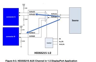
In my customer design, source is BMC AST2600, SINK side is two mini displayport connector(rear and front).

They use HD3SS215IRTQT for switching.

Customer would like to check AC decoupling location.

As BMC design guide,

But in HD3SS215IRTQT spec,

Do you have any suggestion for this design?

It seems the AC DECAP on AUXP/N need close to connector for BMC design guide, and close to mainlink for HD3SS215IRTQT design procedure.

  • Hi,

    What is the max data rate for this particular design? Please note the HD3SS215 can only support up to DP HBR2 (5.4G). For DP higher data rate, please consider the HD3SS214 which can support HBR3 at 8.1G. 

    The HD3SS215 requires a bias voltage, the designer must place the capacitors on one side of the switch. In the HD3SS215 example above, the bias voltage is provided by the pullup/pulldown resistor to VDD. if you move the cap from the source to the connector side, then the bias voltage is provided by the source and you have to make sure the source bias voltage meets the HD3SS215 common mode voltage requirement (0 to 3.3V).

    Someone also pointed out a design pitfall with the example above. Please see this e2e post for detailed discussion, https://e2e.ti.com/support/interface-group/interface/f/interface-forum/1000281/hd3ss215-how-to-treat-aux-pin-when-selecting-either-of-two-output?tisearch=e2e-sitesearch&keymatch=hd3ss215#

    Thanks
    David

  • Hi David,

    1. What is the max data rate for this design? Please note the HD3SS215 can only support up to DP HBR2 (5.4G). For DP higher data rate, please consider the HD3SS214 which can support HBR3 at 8.1G.

    => 2.7G max from BMC AST2600A3

    it seems the HD3SS215 can meet our requirement, right?


    2. The HD3SS215 requires a bias voltage, the design must place the capacitors on one side of the switch. In the HD3SS215 example you provided, the bias voltage is provided by the pullup/pulldown resistor to VDD.

    If you move the cap from the source to the connector side, then the bias voltage is provided by the source and you have to make sure the source bias voltage meets the HD3SS215 common mode voltage requirement (0 to 3.3V).

    => After check the datasheet of AST2600A3,


    It seems I can place AC cap close to connector side if VDD bias voltage is during 0-3.3V,right?

  • Hi,

    1. HD3SS215 can support 2.7Gbps data rate.

    2. I am not referring to the device power or VDD bias voltage, I am referring to the actual DP main link and AUX signal common mode voltage which should be 0 to 2V, please double check the AST2600A3 datasheet to confirm.

    Thanks

    David

  • Hi David,

    Double check with spec, it seems follow standard criteria(displayport spec 1.1a).

    Thus, the voltage range meet what you mentioned 0 to 2V.

    So put AC cap on Auxp/N close to connector side, on TXP/N close to BMC side. (follow BMC design guide)

    Is it ok?

  • Hi,

    Please see the picture for the AUX caps location.

    I would also recommend they place the TXP/N caps on the connector side. I know this is different from the BMC design guide. But having the caps on the connector would ensure the HD3SS215 MUX common mode voltage is set by the BMC. 

    Thanks

    David 

  • Hi David,

    In customer design, the source is BMC, SINK are front side display port and rear side display port.

    For below setting


    If they need auto detect and switch front and rear with each other. (Front side is First priority)

    Below is the design,

    AUX_SEL => 10K PU and 10K PD for M.

    How to set Dx_SEL?

    Can they use HW control (MOS or logic) by using HPD of front side display port?

    Or need FW control??

  • Hi,

    You can use HPD from the front and the rear as the input to drive the DX_SEL selection. An external circuit is also needed to determine that the front is the priority if the HPD from both the front and the rear are high. 

    Please also note that when HPD from both the front and the rear are high and you toggle the DX_SEL, there is no transition of HPD going from high, low, and then high. But you need to pull the HPD low and then high so the BMC source knows there is a change in the sink device.

    Thanks

    David

  • Hi David,

    Is it no problem if we use HPD to control Dx_SEL?

    Customer mentioned the DP1.4 spec, it seems that HPD is not only a hot plug detect but also a interrupt signal (HPD_IRQ).

    And it’s a Hi/LOW pulse such as reset signal.

    Because they can not found such as present function to control displayport cable be plug/present or not.

  • Hi,

    HPD is used by the Upstream device to detect that a downstream port on the device has been connected to another device (the downstream device).

    The HPD interrupt is a low-going HPD pulse of 0.5ms → 1ms in duration.

    The HPD is seen as disconnect if low-going HPD pulse is longer than 2ms in duration. 

    The external circuit has to differentiate between the HPD interrupt and HPD disconnect and then properly drive the DX_SEL. 

    Thanks
    David