This thread has been locked.

If you have a related question, please click the "Ask a related question" button in the top right corner. The newly created question will be automatically linked to this question.

LVDS 1224B "false-lock" at open-input

Other Parts Discussed in Thread: SN65LV1224B, DS25BR110

Hello,
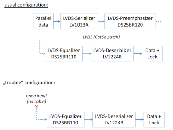
we are currently facing a little hardware problem, including one of your products, the SN65LV1224B LVDS de-serializer. Please find a structural overview in the drawing attached.


The problem is as follows:
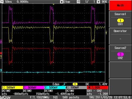
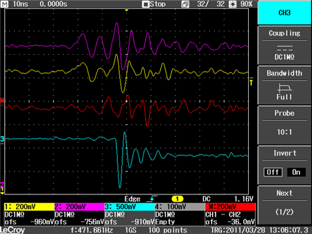
In an usual configuration, the data is received correctly, but if no cable is attached to the receiving unit, a "false-lock" occurs and fades spontaneously on the output of the de-serializer, resulting in random false-data on the output of the de-serializer. In this state, it seems that the rate of "lock"- and "non-lock"-time varies depending on the frequency of the reference-clock of the de-serializer (tested 10MHz up to 40MHz) AND the level of equalization of the (National Semiconductor's) DS25BR110. Any way, this is not the behavior we expected. We thought that an open input (no cable) results in a constant inactive "lock" signal and tristate-data.

Could you imagine, that there is a problem with the de-serializer? Maybe we've got a wrong configuration? What do you think?

It is worth to note, that

  • the NSC's DS25BR110 receive buffer is located closely on-board to Texas Instruments' LVDS-de-serializer LV1224B and that
  • there are 6 similiar receiving units on the board next to another, each of it may have a cable connected or not (hot-pluggable)


Thanks in advance,

yours sincerely, Harald Schweitzer

  • Hi Harald,

    Is it possible for you to take a look at the LV1224B's serial inputs on an oscilloscope when the cable is disconnected?  If the line is held at a constant level, then the deserializer should indicate that lock has been lost.  However, it doesn't look like the equalizer used has open-circuit failsafe detection.  This means that its output state will be undefined when no differential input is present.  It is possible that the equalizer output is toggling in such a way that the LV1224B falsely detects it as data.

    Best regards,
    Max Robertson
    Analog Applications Engineer
    Texas Instruments
    m-robertson@ti.com

  • Hi Max,
    thank you very much for your response.

    Well, I did my best to provide you with two scope plots. They are not perfect, but might be helpful.

    First, a plot is shown with an input device attached. The lower signal (CH3) is the "LOCK" output of the LV1224B, and the upper two signals(CH1, CH2) are the D+ and D- inputs. The signal in-the-middle is the MATH-output of the oscilloscope (CH1-CH2). As you see, the signal looks good:

    For the second plot, there was no input device attached, meaning open-input for the equalizer. The signals are the same as above. As you can see, there are peaks on D+ and D-, resulting in a differential voltage of around 200mV (peak-peak). After these peaks, the LV1224B decides to lock and drives "LOCK" low:

    Could you imagine, that this short periode of 200mV is enough for the LV1224B to lock onto this signal correctly? I'm not sure if I got the point right, but I think the datasheet says something about +/-50mV threshold. If this is it, the LV1224B does work correctly, and the problem seems to be the equalizer. I can't find a answer to what the equalizer does if its input are below its low/high-thresholds. But well, this is not a question to be discussed in here :-) We are currently in contact with the NSC support as well, maybe we can get an answer for it there.

    What do you think about the over-all problem, Max? Were the plots helpful? Please let me know if you need more/other plots.

    Thanks in advance,
    Harald

  • Harald,

    The second plot seems a bit strange to me.  The /LOCK pin is an LVCMOS/LVTTL-level output, so when it is active it should either be above 2.2 V (high) or below 0.5 V (low).  In the second plot, though, it looks like the difference between the high and low levels is only about 500 mV.  What do you have connected to this pin?  Is it connected to a high impedance, or could something else be driving this pin?

    You may want to monitor the power supply when this false lock condition is occurring as well.  It looks like there is some correlation between the noise you are seeing on each signal, and it is possible the signals are tracking some noise or ripple on the supply.

    The LV1224B does have some failsafe detection (described on p. 5 of the datasheet) that will drive /LOCK high when the input is no longer actively driven.  I would guess, though, that since the equalizer is not disabled (made high impedance) it is still technically driving the serial input and thus the LV1224B is treating the noise on the line as data.  You are correct that the differential threshold voltage for the LVDS input is only 50 mV when it is being driven with a signal.

    Would it be possible for me to take a look at your schematic?  You can send it to me via direct e-mail or private message if you do not want it posted on this (public) forum.

    Best regards,
    Max Robertson
    Analog Applications Engineer
    Texas Instruments
    m-robertson@ti.com

  • Hi Max,
    thanks for your answer.

    You are right, the level of the /LOCK signal seems to be incorrect and I will re-check this one. May this is due to my measurement setup (low board-dimensions and equipment). This pin is connected to an input of an FPGA.

    Additionally, I'm going to check the power supply as well. Thanks for the hint.

    I agree with you - it seems that the equalizer is driving the serial input, although there is no input connected to it. It should be possible to make the output of the equalizer high-impedance, then the LV1224B probably would detect it correctly as open-input. We are currently wating for response of the NSC support, maybe we get a hint there. Any way, I'm going to send you the schematic via private-message.

    Kind regards,
    Harald