This thread has been locked.

If you have a related question, please click the "Ask a related question" button in the top right corner. The newly created question will be automatically linked to this question.

DP83867IR: Interface forum

Part Number: DP83867IR

DP83867IR: communication problems.
Hi all,

in our machine we have the DP83867IRRGZ as ethernet controller and Xilinx XCZU5EV as FPGA.

We have connect our machine to an external ethernet switch: TP-link TL-SG108 and we have connected a PC to the external ethernet switch. The cable between EUT and ethernet switch pass through the clamp.

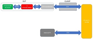
During the immunity test we have done a ping command between EUT and external PC, at 1Gbps.

The immunity test was EN 61000-4-4 (burst level 0.5kV (repetition freq. 5kHz), CLAMP on Ethernet cable).

When we apply the burst, the ethernet connection fails, when the burst stops the ethernet connection is restored.The same test @10/100Mbps ends successfully.
If we increase the voltage to 1kV, the ethernet connection loss the "link" and, at the end of burst, the connection doesn't resumes.

We have done the same test Xilinx eval board (HW-Z1-ZCU104 Evaluation Board(XCZU7EV-2FFVC1156)) and the result is the same: @1Gbps, when we apply the burst, the eternet connection falls.


Have you any suggestions in order to increase the noise immunity?

Thanks in advance,

Diego.

  • Hi Diego,

    My thoughts are that this is most likely a board dependent failure. I am going to copy and paste some layout optimization guidelines below! (These are from an app note that will be released online soon.)

    MDI Traces
    The total length of each MDI trace should be less than 2 inches, or 2000 mils. The traces should be lengthmatched
    within 20 mils for 1G transmissions and within 50 mils for 100M or 10M transmissions. The number of
    vias and stubs on the MDI traces should be kept to a minimum.
    The typical impedance should be a 100 Ohm differential with a +/- 10% control. An impedance mismatch will
    decrease throughput, sometimes significant enough to cause communication failure. The mismatches cause
    signal reflections that prevent maximum power from being transferred beyond the point of reflection. The
    impedance on the MDI traces may need to be adjusted to match the impedance of the cable. Verify the cable
    impedance using the cable's datasheet.
    If "w" equals the width of the MDI trace, ground planes on the same layer should be distanced at least 3*w from
    the MDI trace. The preferred distance is 5*w from the MDI trace. Designing this distance between the MDI trace
    and the ground plane prevents unwanted capacitive impedance.

    Continuous ground is recommended on the layer under the MDI traces. The ground plane should be cut, or
    void, only under the components on the trace. Some of these componets include transformer/magnetics, chokes,
    AC coupling capacitors and ESD diodes. For automotive applications, an "all-layer" void is recommended, but
    a "two-layer" void is the minimum requirement. The "two-layer" void would include the layer the component is
    on and the layer below. For standard applications, a "two-layer" void is recommended. The distance between
    the edge of the component and the edge of the void should be about 20 mils for most applications. Some
    applications can have a shorter distance, while other may require a larger distance. Please use the design's
    EMC requirements to determine the best distance.

    magnetic isolation

    No metal should be under the magnetics on any layer. If metal is needed under the magnetics, it must be
    seperated by a ground plane at the least. Metal under the RJ45 connector with integrated magnetic is allowed.
    The figure below shows a layout example with no metal below the magnetics.

    GND planes

    Place ground planes where possible and use stitching vias throughout the board to create short return paths.

    Earth GND isolation

    Earth ground should be isolated from the rest of the board by at least 20 mil keepout on all layers. The figure
    below shows an example of this.

    Also, placing a capacitor and a high value resistor (1MOhm or higher between earth gnd and normal gnd helps with noise issues)

    Thanks,

    Lysny

  • Hi Lysny Woodahl,

    at hardware level it's all ok, impedance, distance and so on.. We are made the signal integrity analisys before made the boards..
    In order to understand what is the problem, we have done some test and some verifications as explained in the application notes:


    - “DP83867 Troubleshooting Guide”
    - “How to Configure DP838xx for Ethernet Compliance Testing”

    In all test the signals are compliant with the results shown in these application notes.

    We have made some test changing the registers value:

    1. RGMIIDCTL: we have changed the amount of delay on TX and RX signals. The ethernet connection work fine in a lot of configuration of these registers.. When the value of the register fall below 0x33 or exceeds the value 0xEE, the ethernet connection stops. Since the connection doesn't fall with a lot of values of delay, we can say that the RGMII has robust signals..
    2. PHYSTS: by default the chip has autonegotiation on.If we try to disable the autoneg an then set the speed, the link fall and the ethernet connection doesn't resume.. We can't understand this fact..

    Have you got any suggestion in order to investigate about our problem connection?

    Can we check some register value?

    Do you know of a similar problem on this ethernet phy?

    Best regards,

    Diego.

  • Hi Diego,

    Could you please confirm that the last three design recommendations are complete in your design? If you are able, can you share your layout design to confirm that these are included in your design. The design will not be able to pass these tests without these recommendation.

    Thank you,

    Lysny