This thread has been locked.

If you have a related question, please click the "Ask a related question" button in the top right corner. The newly created question will be automatically linked to this question.

DP83867IS: Both the DP83867IS communication,there is a certain probability of no link phenomenon

Part Number: DP83867IS

dear,

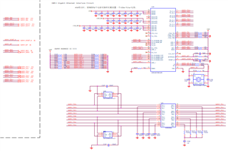
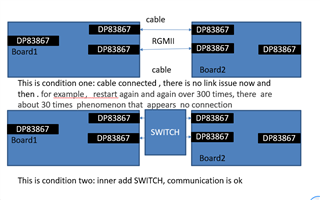
I use network cables to link the both DP83867 board (PING each other ), there is a certain probability of no link phenomenon;  for example,restart again and again over 300 times, there  are about 30 times  phenomenon that  appears  no connection , the issue  is same  in RGMI or SGMI  interface, and the both DP83867  PCB of  boards are same,  the schematic is as below,  I use 3 channel power supply for PHY chip,that is VDDA1P8 ,VDDA1P0,VDDA2P5, the timing :VDDA1P8  is 200ms earlier than VDDA1P0 and VDDA2P5; 

however, I tried to add a switch both the DP83867 board, it is ok,no problem,other operation environment  including clock are not  changed; could you help me analyze what is wrong with it ?

  • Hi,

    Could you please send a higher resolution photo and I can look into this more? 

    Thanks,

    Lysny

  • Dear,

    sorry for that , the two interface mode RGMII & SGMII share for you , help me double check ;

    13-SGMII_Gigabit_Ethernet.pdf05-Gigabit_Ethernet.pdf

    by the way, I also did the test : Two pieces of the board of one of the gigabit interface, the application mode of SGMII, two gigabit so use back line cross connected, in the process of testing speed, working at the beginning, then ready to test a night time, but this morning after the discovery, the interface is suddenly not LINK at some point, until now still no LINK,that is, it doesn't automatically recover.

    then , Keep the power , We are trying some verification, when one of the boards is forced to 10M and 100M, it can LINK, it can also PING, but if it is forced to 1000M, it will not LINK.,I also add the automated negotiation , it is ok.  but yesterday it is running , suddenly at some time, it is not link, and no automatically recover, it is serious issue。

    Note: actually my design no matter hardware or software, it is automated negotiation。 

  • Hi,

    Thank you for the images!

    I would like to clarify the issue you are seeing. From what I understand, when the two boards are connected and then powered on, autonegotiation does not negotiate to 1G? Is this the core issue that is occurring?

    And this same issue is occurring for both the SGMII interface and the RGMII interface? Are the SGMII and RGMII interfaces part of the same system? Or are these two separate projects? If you could also provide a block diagram, that will help me visualize the setup!

    Thanks,

    Lysny

  • Hi ,Lysny:

    first, this is same one project , no matter RGMII or SGMII . so it is same system, the core issue is that there is a certain probability of no link phenomenon.  the details as below.

     it is  two pieces of the board of one of the gigabit interface, the application mode of SGMII, two gigabit so use back line cross connected, in the process of testing speed, working at the beginning, then ready to test a night time, but this morning after the discovery, the interface is suddenly not LINK at some point, until now still no LINK,that is, it doesn't automatically recover.

  • Hi Lysny:

    add simple block discribed 

  • Hi Cooper,

    Thank you for the block diagram and clarification. Could you please enable Fast Link Drop, and share if the FLD Status bits are providing any information on why the link is dropping occasionally? Please make sure the FLD sources are also enabled.

    Thanks,

    Lysny

  • Hi Lysny:

    I configured 0 x 002D register,to write 0 x 4000,but I found DP83867IS has no FLP signal,and I also found there was no reference DC value.

    then I refer to register 0x0000,normal is 0x1140,  abnormality is 0x1940(it goes into power down mode

    I do not know why it goes into power down mode , can you give me some advise or suggestion ?

  • Hi Cooper,

    You can read back 0x2D to make sure that all the FLD modes are enabled. If none are enabled, FLD will not provide us any information. 

    Also, my suggestion is that there is a signal on the POWERDOWN_INT pin that is causing the power down. Could you please either check or provide the schematic so we can look into it?

    Thanks,

    Lysny

  • Hi Lysny:

    When the two boards are abnormal during the speed measurement, use ethtool to read PHY status as follows:

    Abnormal board:

    normal board:

    It can be seen from the figure that the power down bit in the register 0000 of the abnormal board is set to 1.

    In addition, the value of the 0x002D register of the two PHYs is 0000.

    What kind of problems will cause the current phenomenon. Power-on sequence or power-off sequence?

    Can you help guide the general direction of a problem analysis.

    Thanks

    Jerome

  • Hi Jerome,

    As mentioned above, please check the power down int pin on your design. Also, you could provide a copy of the schematic layout.

    Thanks,

    Lysny

  • Hi Lysny,

    The power down int pin connected to FPGA GPIO, no control during speed testing and remains high. 

    The schematic diagram is shown in the pdf attachment in the previous question. 13-SGMII_Gigabit_Ethernet.pdf

    I think the PHY may be working in a certain error mode, which caused the power down. 

    In this circuit design, PHY works in three power mode,  the power on timing :VDDA1P8  is 200ms earlier than VDDA1P0 and VDDA2P5; VDDIO is powered on between VDDA1P8 and VDD2P5. When the board is powered off, several power supplies are powered off at the same time. Whether this timing can cause the PHY to enter an abnormal mode, or where should we analyze the problem?

    Thanks

    Jerome

  • Hi Jerome,

    Would you be able to measure the power down pin, the power rails and reset during this link drop and look for any abnormalities? I don't see an error on that pin in the schematic.

    Thanks,

    Lysny

  • Hi Lysny,

    After testing, the power down pin, the power rails and reset during this link drop are no problem.

    I want to ask three questions.

    1. The relationship between the power supply of VDDA1P8 and the internal power-on reset of the PHY chip?

    2. What error will occur if the power-on sequence in the three power mode is incorrect?

    3. If the internal power-on reset is abnormal, what error will occur?

    From which register can I read the error information mentioned above?

    Thanks

    Jerome

  • Hi Lysny:

    1. currently ,  the power down pin is no problem ; so could you analyze why it will go in the power down mode.  

    2. about Jerome three questions , please kindly give your points , many thanks~

    3. option , I explain that there is a condition,   at first, customer chooses  two  power mode,  but VDDA1P8 is connected , the datasheet shows if VDDA1P8 is not used, it should be floating ,  so customer has to choose three power mode, he put 1.8V add in VDDA1P8 Bus, and 200ms earlier than VDDA2P5 & VDDA1P0; I want to know this will  cause the reason for no link ;

    4. if i change to two power mode,  will it solve the question? 

  • Hi Jerome and Cooper,

    Glad to hear that the power down link drop is not occurring. 

    Here are my responses to the questions Jerome asked:

    1. I'm not entirely sure what you mean here. Both the 1.8 V supply and the reset have different functions for the PHY.

    2. The most common errors would be a slow start up or link time or failure to link. (Just to confirm the issue that was seen was a link drop, not a failure to link)

    3. The straps might not be correctly latched, or the internal state machine might be in the incorrect state. If you are concerned the POR is not operating correctly, you could test performing a software reset after each start up and see if you are able to capture the link drop with or without this additional reset.

    For Cooper's questions:

    1. I can't analyze why the device is going into power down mode without more information. We would need to capture more info during this power down event.

    3. In the datasheet, there is a note the describes that if the 2.5V line is ONLY connected to the single 867 PHY, 1.8V can be powered on first. But if it is not, the 1.8V and 2.5V power rails must become stable within 25 ms of each other, recommending the 2.5V line to be first.

    4. Which question are you referring to?

    Thanks,

    Lysny

  • Dear Lysny:

    thanks for your feedback. if my customer the 1.8 power rails start at first and earlier than 2.5V power rail in three -supply mode operation, I want to know what it causes ?  maybe it cause the no linking issue ?  

  • Dear Lysny:

    Just I said  my question in three- supply mode operation; I also want to know , in two-supply mode, if VDDA1P8 is connected, not floating , what  it will cause ? because my customer only finds the error design  in VDDA1P8 power rail. 

  • Cooper,

    The most common errors would be a slow start up or link time or failure to link. (Just to confirm the issue that was seen was a link drop, not a failure to link)
  • Hi,

    I also am not sure what you are asking? Are you asking what 2 supply mode causes?? The device can support 2 supply mode, as stated in the datasheet. I'm not sure what else the question is.

    Thanks,

    Lysny