This thread has been locked.

If you have a related question, please click the "Ask a related question" button in the top right corner. The newly created question will be automatically linked to this question.

TPS65983B: Technical Question for PD Controller TPS65983BAZBHR

Part Number: TPS65983B
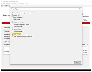
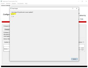
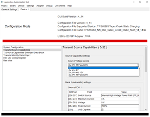
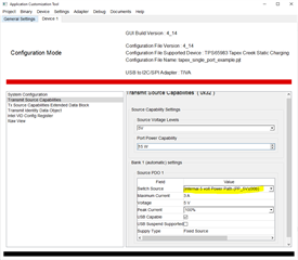
Currently, we are using the TPS65983BAZBHR PD controller together with the Titan Ridge JHL7440 Thunderbolt 3 with both chipset sharing the same external SPI flash. We are using the Imaginarium2 v4.26.1 to merge the firmware of both Titan Ridge and PD controller. We also verified and made sure that all our power supplies are good. . When we connect the thunderbolt cable to my hardware from the PC, there is no thunderbolt connection detected in my PC. We confirmed that the thunderbolt port from the PC is working with other thunderbolt devices. 
1) How do we know that the PD controller is working correctly?
2) How do we know that the firmware is successfully loaded into the PD controller?
  • Hi,

    Do you have a PD Analyzer? Find in the link below:

    If you have this already, please take PD logs to verify the Thunderbolt mode entry.

    Do you have an I2C analyzer? You can get one similar to the one in the link below:

    • https://www.saleae.com/
    • Please capture the I2C log on the I2C connection between the TPS65983B and the JHL7440. This will tell us if the communication is successful.

    You can check the guide below as a reference to probe some of the signals on the board to verify that the PD controller is up and running

    https://www.ti.com/lit/pdf/slva713

    Jacob

  • Hi,

    We do not have a PD analyzer and I2C analyzer. However, from the oscillscope, we can captured that there is some I2C activities upon power up between TPS65983B and the JHL7440. Can you let us know what is the expected I2C activity?

    Also, I found out that there are no signal toggling on the CC1 and CC2 of PD controller in our board when they are not connected.

    I had verified that there is an image in the flash. This flash is working on the Tapex Creek TI83 eval board when we mount on it. Our hardware schematic is very similar to the Tapex Creek design.

    I checked that there are 3.3V on the input and LDO_3V3 and there are 1.8V on the LDO_1V8D and LDO_1V8A.

    Does it mean that the PD controller is still in BOOT mode? If yes, what could cause the PD controller stay in BOOT mode even after we had verified that the same flash component is working fine on the eval board?

    If the PD controller is not in BOOT mode, what are other possible reasons?

  • Hi,

    If you followed the reference schematic you should not run into any issues especially if you verified the flash image on Tapex Creek. Without verifying the I2C and/or PD communication there is a limit to what we can track down. Most o-scopes have digital inputs, you could use that to probe the I2C traffic to decode it. 

    Could you try probing the SPI_CLK from the PD controller to the SPI flash? You should see the PD controller start to read from the flash at power up. 

    To confirm are you using the tool in the link below to generate the PD controller FW:

    https://software-dl.ti.com/secure/software/hval_acs/TPS65983-SECSW-OPN/windows_64bit_TPS65983_Thunderbolt_application_customization_4_14.exe

    Jacob

  • Hi,

    Attached  is our PD controller firmware setting and the project file However, the firmware is not working in our hardware so I am requesting whether you share with me the firmware setting of PD controller firmware for Tapex Creek reference design ? We want to customize the firmware for our hardware use case from the Tapex Creek PD firmware setting. For your information, we are using only the PP_5V for for source PDO in our design. We are not using the PP_HV and PP_EXT. Our design only uses single port Thunderbolt 3 to PCIE We will not be using the Display port and USB where they are left unconnected. We are also not using the power charging and the power is self powered. Can someone from the technical team advise us on the firmware setting as used in our application?

    PD_FW_Setting.pdfPD_0.pjt

  • Hi,

    Where is the confusion? All of the settings you need are in the prompts and in the template file, check the images below. 

    Have you successfully merged the PD controller FW and the Thunderbolt NVM? As I mentioned before you will have to check some of the steps above, to point us to the where your system if failing. 

    Jacob

  • Hi,

    Below are the I2C traffic that I decoded upon powering up the board. As I mentioned, the CC1 and CC2 are not toggling. Is it due to the firmware setting not set correctly? Can you advise from the firmware setting I shared from the reply previously? Also, I want to ask that there are 'Internal 5 volt Power Path (PP_5V)(00b)' and 'Internal 5 volt Power Path (PP_5V)(10b)' option from the Switch Source setting. What are the different between them? Which should I choose if my hardware is using the PP_5V for for source PDO in our design?

    1) ACK low, Write

    0

    1

    1

    1

    0

    0

    0

    0

    0

    0

    1

    0

    1

    0

    0

    0

    0

    0

    Addr

    W

    Ak

    Data

    Ak

    38


    50


    2) ACK low, Write

    0

    0

    0

    0

    0

    0

    1

    0

    0

    0

    0

    0

    0

    0

    1

    0

    0

    0

    Addr

    W

    Ak

    Data

    Ak

    01


    04


    3) ACK low, Write

    0

    0

    0

    0

    0

    0

    0

    0

    0

    0

    1

    1

    1

    0

    0

    0

    0

    0

    Addr

    W

    Ak

    Data

    Ak

    00


    70


    4) ACK low, Read

    0

    1

    0

    1

    1

    1

    1

    1

    0

    0

    1

    1

    1

    0

    0

    0

    1

    0

    Addr

    R

    Ak

    Data

    Ak

    2F


    71


    5) ACK low, Write

    0

    0

    0

    0

    0

    1

    0

    0

    0

    0

    0

    0

    0

    0

    0

    0

    0

    0

    Addr

    W

    Ak

    Data

    Ak

    02


    00


    6) ACK low, Write

    0

    0

    0

    0

    0

    0

    0

    0

    0

    0

    0

    0

    0

    0

    0

    0

    0

    0

    Addr

    W

    Ak

    Data

    Ak

    00


    00


    7) ACK high, slave not recognize

    0

    0

    0

    0

    0

    0

    0

    0

    1


    Addr

    W

    Ak

    Data

    Ak

    00


  • Hi,

    I will review your project and let you know if I find any inconsistencies. In terms of the I2C data the thunderbolt controller will write to register 0x50 and read 0x5F. In the decoded log I see that you have 2F, can you please double check you analysis.

    Jacob

  • Hi,

    I double check it and it really show 2F. I am thinking that my issue is due to the configuration in the PD controller firmware. Could you show and guide me on the setting on how to set and configure PD controller to single UFP, single DFP and dual port? 

    Thanks.

    Isaac

  • Hi,

    I looked at your project and the only thing that seems out of place is the source capabilities. It should be 5V 3A for any TBT DRP port. 

    Please try this is as a reference. I merely used the steps above to create this. Be sure to save the low region image and merge it in Imaginarium.

    tapex_single_port_example.pjt

    Jacob

  • Hi Jacob,

    Actually our design only cater for a max of 1A and aim to be used as UFP port. Can you send me a reference for UFP configuration that I can refer to?

    If it helps, we can share the schematic to you.

    Thanks.

    Isaac

  • Hi Isaac,

    If you have a port that supports power as a source you will at as minimum have to support 5V @ 3A.

    This type of design may not pass TBT3 certification. Has the Intel team review this design?

    Jacob

  • Hi Jacob,

    We are actually not sourcing any device. We are just using the TBT for communication purpose. So it is ok to set PP_5V PDO  as 5V @ 1A right?

    Yes Intel team had helped reviewed this design.

    Also, I tested various configuration on the PD controller but I notice that the CC line is not responding to the PC when we plug in the TBT cable. It is like the PD controller is not giving any response to discover the identity when it is connected to the PC. What could be the possible root cause for this behavior?

    Isaac

  • Hi Jacob,

    We got 2 prototype with the PD controller. We just found out the the VBUS for both prototypes are shorted to ground. What could be the possible reason for the VBUS to short to ground? Will wrong settings in the configuration cause the VBUS to short to ground?

    Thanks.

    Isaac

  • Hi Isaac,

    I think since your port will be DRP, to pass the TBT certification, you need 5V/3A capability. 

    For your VBUS being shorted to ground, this shouldn't be happening. If there are no contracts negotiated then VBUS could be at 0V. It could be a schematic or layout issue. 

    Jacob is currently out of office, once he is back next week he will be able to assist you and confirm this.

    Thank you,

    Hari

  • Hi Jacob, Hari,

    Could you help us review the Thunderbolt portion of the schematic with the PD controller? As I had mentioned before, the design in the VBUS portion of our hardware is a little different from the Tapex Creek reference design since we are not sourcing any device. 

    Thanks.

    Isaac

  • Hi Isaac,

    We got the schematic and will review. 

    Jacob

  • Hi Isaac,

    I see that in your design you have the PP_5V0 used to provide VBUS. The project file that I had attached has this configured correctly.

    Jacob

  • Hi Jacob,

    I found the cause failure in my circuitry. Found out that there are shorts in the connector. After cleaning the Pins short in the connector, the PD controller is working fine. Thanks and appreciate for the help and support that you had given. 

    Thanks.

    Isaac