


Dear team,
My customer has three questions as below, could you please help answer these questions?
1. Under what circumstances will cause our chip to fail? Under what circumstances will cause a single channel to fail? If one channel fails, will other channels be affected?
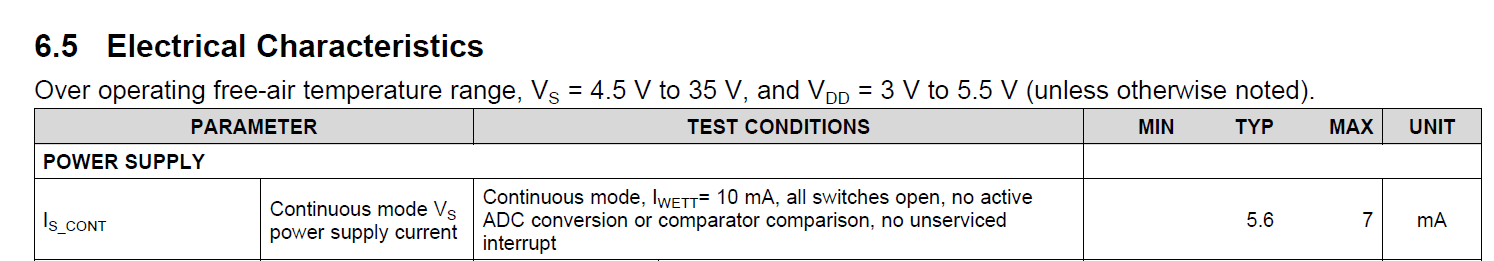
2. In continuous mode, if the wetting current of every channel is 10mA, then our device will always consume 240mA current(24 channels). Then the total consumption of our device is 240mA+7mA, right?
3. In the datasheet, there are two switches, analog switches and digital switches. For our device, the only difference between these two switches is that analog switch may have several states while digital switch only have two states, right?
Thanks & Best Regards,
Sherry
