This thread has been locked.

If you have a related question, please click the "Ask a related question" button in the top right corner. The newly created question will be automatically linked to this question.

TPS65982DMC: Firmware to be used with Gorilla Creek reference design.

Part Number: TPS65982DMC
Other Parts Discussed in Thread: TPS65988DK

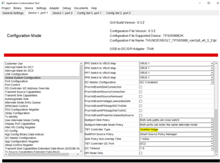
We are building a TBT device based on Gorilla Creek reference design and are using the this DMC. It's unclear to us what firmware we should use and is it necessary to customize the firmware with TI tool? I have the tool already downloaded and installed.

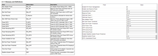
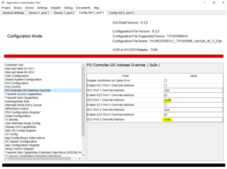
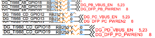
For the design we have connected all the main parts (DMC, PD controllers, buck-boost etc.) like in Gorilla Creek reference design. However it's unclear to me what are all the functions of the DMC. Is it responsible for example on uploading the FW to PD controllers and do we need to somehow configure those with the tool or is it built in on the DMC firmware?

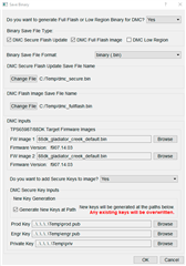
Can we just use the tool to make a new project for TPS65982DMC Gorilla Creek and export the binary as is for flashing the memory?

  • Hi Jaakko,

    Please check the link below, this covers how to generate the binaries for Gorilla Creek. If the audio only comes through please download the video and play.

    https://software-dl.ti.com/secure/software/app_psil/pi/TBTDEVICE-DESIGN/How_to_save_988DK_982DMC_Secure_and_Full_Binaries.mp4

    Jacob

  • Thanks for the link. Could you also link up to date user guide for the DMC. I have a draft version that is missing some parts. I need to be able to configure all the power ratings etc. settings correctly.

    When saving the DMC firmware do we need to make our own signing keys somehow or can we use the suggested ones? Private key probably would be needed for the secure firmware?

  • HI Jaakko,

    All of the default configuration will be set correctly for Gorilla Creek in the template. Unless you need to make specific changes for a modified design. Most of the power sections should be described, is there any field that is in question?

    If you plan on doing the secure update over USB you will have to use your own keys, which can be generated by the tool. 

    1. Generate the DMC Secure Flash Update binary and secure keys
      • This must be the first step taken since otherwise the DMC will reject the update because the keys don't match
      • The customer must be sure to keep these keys in a secure location and not lose them, otherwise they will not be able to perform a secure update in the future
    2. Generate the DMC Full Flash Image binary
      • Provide the GUI with the Secure Keys generated in Step 1
      • You must provide the exact keys generated in Step 1 or the DMC will reject the update
    3. Flash the 982DMC using the DMC Full Flash
      • This sets the customer's custom Secure Keys on the product so they can issue secure updates in the future using the keys they generated in Step 1
      • This is done in the GUI by going to Binary -> Flash from Binary File and following the dialog prompts
    4. Now the 982DMC is Secure FW Update capable using the customer's Secure Keys
      • To test this, they can perform the Secure Flash Update and provide the Secure Flash Update using the DMC Secure Flash Update binary generated in Step 1

    All of these steps can be combined into a single step by checking both the DMC Secure Flash Update and DMC Full Flash Image options in the Save Binary dialog, and checking the Generate New Keys at Path option under DMC Secure Keys Inputs. This generates all of the collaterals that the customer needs for success:

    1. DMC Secure Flash Update binary: dmc_secure.bin
      • Used to perform the secure update. When the customer needs to issue a secure update, they'll come back to this dialog and provide the private key they generated during this step instead of generating new keys
    2. DMC Flash Image binary: dmc_fullflash.bin
      • Used to perform the initial flashing of the 982DMC. This sets the baseline FW and the keys that will be used to perform the Secure Update in the future. Without this initial binary, there's no way to perform a secure update as the keys will be unknown
    3. Generate New Keys at Path
      • Used to generate a brand new set of custom keys that the customer must keep track of in order to create and issue secure updates. These will be flashed onto the device and used to perform the secure update key check
    4. Prod Key: prod.pub
      • The production public key flashed onto the device
    5. Engr Key: engr.pub
      • The engineering public key flashed onto the device
    6. Private Key: priv
      • The private key that only the customer knows. This is used to create a Secure Flash Update binary that will pass the cryptographic check against the public keys that are flashed onto the device. The customer must use this private key to generate new Secure Flash Update binaries in the future

    Jacob

  • We are using Gorilla Creek reference design as basis to our project and did only some minor changes e.g. added more USB devices on the board. We also need to provide a bit more power to UFP than Gorilla Creek is actually designed for. Therefore we need to change some of the settings on the DMC firmware. All the core functions from the reference are implemented in the same way than in the reference design. 

    From the picture you can see that the draft User Guide and the tool differ from each other and the tooltips on the tool are not so helpful on determining what different settings are used for. That's the reason why I asked for an updated user guide that will reflect all the settings that can be configured with the tool. For example the user guide states Max USB Power but on the tool there is two limits for it. Min and max host power are not existing in the tool also.

    Also on the Gorilla Creek reference there is dedicated current measurement for legacy USB ports and its output is connected to DMC directly. However in the firmware it's not enabled. When enabling "System 5V power sense" in the DMC FW tool there is no way to configure the ADC reference so user could adjust that the power calculation will be correct. Also how do I know which one of the Max USB Power limits it will refer to?

  • Hi Jaakko,

    Sorry for the confusion here. Please use the configuration tool as the correct definition. 

    We have some internal descriptions that I can clean up and post on the secure site that show the power manager function and details. 

    Please see the snap shot below for reference:

    Please give us a few days to post this. 

  • Hi Jacob,

    Any estimate when you can post the power manager function and details to secure site?

    Also I found out that the thunderbolt application customization tool is not showing I2C addresses correctly for TPS65988DK. Should I manually force the I2C addresses to same than can be found from Gorilla Creek reference design block diagram (it doesn't show I2C1 addresses though so I probably need to trust that those will be default?)

  • Hi Jaakko, 

    This week has been a little crazy. I will let you know the time line at the close of the week. 

    For the I2C connection to the Thunderbolt 4 Controller, the I2C address is dependent on some of the configuration and not on the pin strapping. 

    For Port A/B it will set the I2C address to 0x38 and 0x3F:

    For PortC/D it has to be overwritten in the register below as 0x48 and 0x4F

    Jacob

  • Hi Jacob,

    Thanks for confirming the I2C addresses. It seems that the general settings sheet cannot be trusted with the addresses as it shows them wrong. So the firmware that tool generates should work out of box without any change when we have connected everything like in the reference design?

    One additional thing I noticed is that the reference design has VBUS_EN and PRWEN signals for PB, PC and PD ports. However when looking at the firmware configuration those are not enabled in GPIO listing and to best of my knowledge GPIOs cannot be used to control PP switches? Is it true that VBUS_EN and PWREN signals has no use in gorilla creek or are those for future purposes when FW evolves?

    To my understanding VBUS_EN is USB-C port power gate control signal from TBT controller (Goshen Ridge) and PWREN signals are power gate control signals from USB2 hub.

  • Hi Jaakko,

    The template file for Gorilla Creek should be the latest and greatest. Please use that as the base line. Correct they are currently not needed in the design. 

    This is actually handled over I2C between the TBT4 controller and PD controller. 

    Jacob

  • Have you had time to put explanations of DMC settings to secure site?

  • Hi Jaakko,

    I have posted the presentation in the secure site. Please let me know if you run into any issues downloading the document.

    Jacob