This thread has been locked.

If you have a related question, please click the "Ask a related question" button in the top right corner. The newly created question will be automatically linked to this question.

TCAN1145EVM: Max SPI clock frequency in sleep mode

Part Number: TCAN1145EVM

Hello,

I am trying to write an Autosar CanTrcv driver for the TI TCAN 114x CanFD transceiver and it is not clear to me which SPI clock frequency can be use during SLEEP mode?

In the datasheet/reference manual (revision SLLSF80A – OCTOBER 2019 – REVISED DECEMBER 2020) it states that the maximum SPI clock frequency during SLEEP mode is 10kHz. In contrast to all the other modes where SPI clock can be up to 4MHz:

In Autosar it is not so easy to switch between different SPI clocks, so in a first attempt I tried to operate the device with 1 Mhz consistently. Then I repeated the same test with 4MHz SPI clock. And the strange thing is that it seems to work (in both cases). Do you know how that can be?

For now I have only tested it only on a TCAN1145 with die version 1.6 (TCAN1145EVM evaluation module).

The SPI settings I used are the following (SpiBaudrate 1Mhz and 4Mhz):

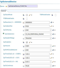
In my test I do following steps:

  • Initialize CAN transceiver (actively writing following register values)
    • MODE_CNTRL=0x04
    • WAKE_PIN_CONFIG=0x04
    • PIN_CONFIG=0x0
    • DEVICE_CONFIG_2=0x0
    • SDO_CONFIG=0x0
    • INT_ENABLE_1=0x60
    • INT_ENABLE_3=0x80
    • SWE_DIS=0x84
    • FSM_CONFIG=0x01
  • Read INT_2 register and clear PWR_ON if set
  • Read INT_1 register and clear
  • Then I put the transceiver into SLEEP mode by writing the MODE_CNTRL register to 0x1
  • From then on every 1000ms registers 0 to 9 (the device_id array index is the register offset) are read. The result is always as depicted below and in my opinion correct

I also checked the SDO pin of the TCAN1145 and visualized the signal coming out of the TCAN1145 and it looks perfectly ok to me.

1MHz:

Blue: SCLK Red: SDO during read of register 0 (result 0x54)


Is that section in the datasheet specifying 10kHz SPI clock in SLEEP mode wrong, or is it coincidence that it works with higher SPI clock frequencies or is there another reason I don’t understand?

Looking forward to your response.

Regards,

Peter Wais

  • Hi Peter,

    The main reason for this speed change is that while in sleep mode, the internal clock source for SPI is inactive. Once nCS is asserted, this clock source needs time to become active and stable before the interface can be used, so the slower data rate is specified to give the device this extra startup time. However, once the internal clock is active, the full 4MHz clock rate is supported. I agree the datasheet does not explain this very clearly and the sleep mode SPI rate spec is misleading. We will be revising this description in a future version to avoid this confusion.  

    The description of sleep mode (10.4.4) explains this behavior more explicitly: "If at least a 10 μs delay is used between pulling nCS low and the start of a read or write the max SPI rate can be utilized." Note that "max SPI rate" refers to 4MHz. 

    I hope this makes it easier for your system to interface with TCAN1145 while in sleep mode as the nCS timing is likely easier to reconfigure dynamically than the entire based clock speed. Let me know if you have any other questions. 

    Regards,
    Eric Schott

  • Hey Eric,

    thank you very much for the explanation.

    Basically according to your answer it still shouldn't work for my test setup but for some reason it does and I would like to understand why.

    As depicted in the SPI settings I am using a 1us (1.0E-6) delay between pulling nCS low and start of the SCLK (SpiTimeCs2Clk). In my understanding that is the time you said should be 10us, or?
    Another thing I forgot to mention was that I am not turning off any power supplies (VCC,VBAT) when entering sleep mode. Maybe I should do that? I could try to turn off VCC or VBAT after entering sleep mode? Do you think that the continuous power supply could be the reason why it works also with 1us nCS to SCLK delay?

    Regards,
    Peter

  • Hi Peter,

    The 10us is the upper limit we define for the needed delay, however the actual time to start-up and stabilize the internal clock may be lower. We specify a large margin here to account for other variables that could impact this timing such as temperature and supply range. I suspect your current setup with 1us delay would not be as reliable across these operational ranges. It's very possible that at nominal levels this 1us delay is sufficient. However, because we specify a longer startup time, this shorter delay may reduce reliability across these operational ranges. For the final implementation, I would recommend that the full specified delay be used to ensure consistent behavior across the operational range of the device. 

    I'm not certain how the Vcc and Vbat supplies impact the behavior of the internal oscillator. I know it is supplied primarily by Vio, but Vbat is still necessary while the device is in low-power mode. If Vbat is removed, the device state machine will be reset so SPI will be unavailable. Vcc is primarily used to supply the transceiver portion of the IC, so I don't suspect the presence or absence of this supply to impact the behavior of the SPI. 

    Let me know if this makes sense and if you have any more questions.

    Regards,
    Eric Schott

  • Now I understand. Thank you very much for the explanation!