This thread has been locked.

If you have a related question, please click the "Ask a related question" button in the top right corner. The newly created question will be automatically linked to this question.

DS90UB941AS-Q1: In Splitter mode, can we configure the parameters(Hsync Front Porch, Hsync Width, etc ) for each FPD link?

Part Number: DS90UB941AS-Q1

Dear TI:

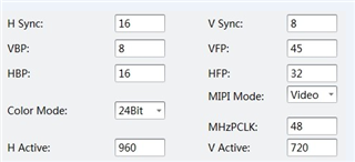
       Can we configure these like configure in pattern test?  We met one issue , UB941 -> two UB948, and only one display is ok, so we want to configure port[x] for each FPD link.

BRs,

Arvin

  • Hello Chen,

    Can you please share the full panel timing parameter spec for both panels including the tolerances? There is some limited adjustment capability for the timing parameters in splitter mode, but not full control so if you share the timing parameters, then I can help you figure out if there is a method to meet the timing of both panels 

    Best Regards,

    Casey 

  • Hi Casey:

        Please check the following parameters, Thanks.

  • Hello Chen,

    The above seems to show only one panel spec but you mentioned there are two panels connected through 941AS. Can you share the timing for both panels? 

    Also is the above showing only one half of the horizontal timing (one OLDI channel?) It looks like a 1920x720 panel size if I were to double the Hactive. 960x720 is a relatively uncommon panel size 

    Best Regards,
    Casey 

  • Hi Casey:

        It's same panel. 

        And for your doubt about size,  you're right. It's 1920*720...

  • Hello Chen,

    So you are trying to drive two identical 1920x720p panels? Can you also provide the timing information for the superframe which you are providing to 941AS which contains both images and the 941AS device configuration?

    Best Regards,

    Casey 

  • Hello Chen,

    Here's my understanding of the current system you have:

    1x DSI -> 941AS -> 2x 948 -> each display 1920x720@60 with PCLK = 96MHz 

    The timing parameters for each display are as follows:

    HACT = 1920

    HFP = 64

    HSYNC = 32

    HBP = 32

    VACT = 720

    VFP = 45

    VSYNC = 8

    VBP = 8

    PCLK = 96MHz 

    In order to generate a superframe to support 2x of these screens, then the source image must have 2x the horizontal timing for each parameter in side by side 3D format and 2x the PCLK of the video for each screen, so that would mean that the DSI source image should have the following dimensions:

    HACT = 3840

    HFP = 128

    HSYNC = 64

    HBP = 64

    VACT = 720

    VFP = 45

    VSYNC = 8

    VBP = 8

    PCLK = 192MHz 

    Then you can run the following example code to init the 941AS to drive the two screens:

    # 3840x720@60 Symmetric Split Example - 2x 1920x720@60
    
    # Video 0 and Video 1 Parameters:
    # HACT = 1920
    # HFP = 64
    # HSYNC = 32
    # HBP = 32
    # VACT = 720
    # VFP = 45
    # VSYNC = 8
    # VBP = 8
    # PCLK = 96MHz 
    
    # DSI Superframe Dimensions:
    # HACT = 3840
    # HFP = 128
    # HSYNC = 64
    # HBP = 64
    # VACT = 720
    # VFP = 45
    # VSYNC = 8
    # VBP = 8
    # PCLK = 192MHz 
    
    # DSI clock = 576MHz
    # DSI Lane Speed = 1152Mbps/lane 
    # 4 Lanes DSI
    # DSI input port 0
    
    import time
    
    UB941AS = 0x18
    
    board.WriteI2C(UB941AS,0x01,0x02) # Reset
    time.sleep(0.1)
    board.WriteI2C(UB941AS,0x01,0x08) # Disable DSI
    board.WriteI2C(UB941AS,0x1E,0x01) # Select port 0
    
    board.WriteI2C(UB941AS,0x4F,0x8C) # 4 Lane Mode continuous clock
    
    board.WriteI2C(UB941AS,0x5B,0x07) # Splitter mode
    
    board.WriteI2C(UB941AS,0x40,0x04) # TSKIP_CNT
    board.WriteI2C(UB941AS,0x41,0x05) # TSKIP_CNT
    board.WriteI2C(UB941AS,0x42,0x40) # TSKIP_CNT
    
    board.WriteI2C(UB941AS,0x56,0x80) # L/R Pixel Processing
    board.WriteI2C(UB941AS,0x32,0x80) # Set 2D Line Size 1920
    board.WriteI2C(UB941AS,0x33,0x07) # 
    
    board.WriteI2C(UB941AS,0x1E,0x01) # Select port 0: 1920x720
    board.WriteI2C(UB941AS,0x36,0x00)
    board.WriteI2C(UB941AS,0x37,0x80) # X Start = 0
    board.WriteI2C(UB941AS,0x38,0x7F) 
    board.WriteI2C(UB941AS,0x39,0x07) # X Stop = 1919
    board.WriteI2C(UB941AS,0x3A,0x00)
    board.WriteI2C(UB941AS,0x3B,0x00) # Y Start = 0
    board.WriteI2C(UB941AS,0x3C,0xCF)
    board.WriteI2C(UB941AS,0x3D,0x02) # Y Stop = 719
    
    board.WriteI2C(UB941AS,0x1E,0x02) # Select port 1: 1920x720
    board.WriteI2C(UB941AS,0x36,0x00)
    board.WriteI2C(UB941AS,0x37,0x80) # X Start = 0
    board.WriteI2C(UB941AS,0x38,0x7F) 
    board.WriteI2C(UB941AS,0x39,0x07) # X Stop = 1919
    board.WriteI2C(UB941AS,0x3A,0x00)
    board.WriteI2C(UB941AS,0x3B,0x00) # Y Start = 0
    board.WriteI2C(UB941AS,0x3C,0xCF)
    board.WriteI2C(UB941AS,0x3D,0x02) # Y Stop = 719
    
    board.WriteI2C(UB941AS,0x40,0x10) # Init DSI Clock Settings (From Section 10.2 of datasheet)
    board.WriteI2C(UB941AS,0x41,0x86) # Init DSI Clock Settings (From Section 10.2 of datasheet)
    board.WriteI2C(UB941AS,0x42,0x0A) # Init DSI Clock Settings (From Section 10.2 of datasheet)
    board.WriteI2C(UB941AS,0x41,0x94) # Init DSI Clock Settings (From Section 10.2 of datasheet)
    board.WriteI2C(UB941AS,0x42,0x0A) # Init DSI Clock Settings (From Section 10.2 of datasheet)
    
    board.WriteI2C(UB941AS,0x01,0x00) #Release DSI

    Best Regards,
    Casey