Other Parts Discussed in Thread: TPS25750, BQ25792
Hi,
I am using TPS25750 in my design. I need to provide charger/device connection intimation to the processor from PD. How to implement this feature in the design?
Regards,
B Sandeep.
This thread has been locked.
If you have a related question, please click the "Ask a related question" button in the top right corner. The newly created question will be automatically linked to this question.
Hi,
I am using TPS25750 in my design. I need to provide charger/device connection intimation to the processor from PD. How to implement this feature in the design?
Regards,
B Sandeep.
Sandeep,
All of the relevant PD information is available through the TPS25750 Host Interface. The link attached shows all of the information that can be read through the I2Cs interface by the host MCU.
Regards,
Chuck
The link was imbedded in the text, but our system does not make it clear. Here is the full link www.ti.com/.../slvuc05.pdf
Chuck,
I have configured GPIO with GUI for plug and ufp_dfp event and programmed the flash. I am not seeing the plug and ufp events in GPIO_STATUS register when i read with aardvark tool.
Please suggest me if I am missing anything.
Regards,
B Sandeep.
Sandeep,
From the Web based GUI, can you click the save configuration button and provide me the JSON. This will allow me to match your configuration on my EVM.
If you need me to help describe the process. I am happy to help.
Hi Chuck,
I am able to read the registers. There is option for selecting SourcePDOContractBit as GPIO event in customization tool but i don't see any register to check the status of SourcePDOContractBit in TPS25750 TRM.
Regards,
B Sandeep.
Sandeep,
There is not a register to read the GPIO status.
You can read the ACTIVE_CONTRACT_PDO Register (0x34) to read the current contract and determine which GPIO is supposed to be set.
Regards,
Chuck
Chuck,
I have configured GPIO0 for ufp_dfp_event_port1 and programmed the same in EEPROM. I can see the direction bit configured as output from the register but GPIO value is not changing even if i connect pen drive in place of charging cable.
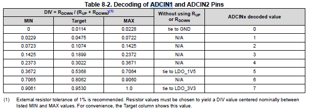
ADCIN1 and ADCIN2 are set to 1V5 in EVM , do i need to change ADCIN1 and ADCIN2 settings?
Please suggest steps on toggling GPIO0 with any of the event available in TPS25750D.
Regards,
B Sandeep.
SAndeep,
ADCIN1 and ADCIN2 being set to 1.5V will configure the part to AlwaysEnableSink mode with I2Cs address of 0x21.
If you are booting from the EEPROM, then I suggest that you set ADCIN1 and ADCIN2 to both be connected to ground VIA a pulldown resistor. This will configure the part into SafeMode with I2C address of 0x21 which is the mode required for EEPROM boot.
Regards,
Chuck
{"questionnaire":{"version":"7.0.1.3","answers":[0,1,1,0,3,1,1,null,1,null,0,8.4,2,0.04,0.04],"options":{},"configID":"0000","vendorID":"0000"},"configuration":{"data":{"selected_ace":[{"register":22,"data":[10,48,48,77,0,0,0,0,0,0,3]},{"register":50,"data":[2,168,42,44,145,1,38,44,209,2,0,44,177,4,0,244,65,6,0,0,0,0,0,0,0,0,0,0,0,0,0]},{"register":51,"data":[2,44,145,1,16,44,209,2,0,44,177,4,0,244,65,6,0,69,65,6,0,0,0,0,0,0,0,0,0]},{"register":92,"data":[1,0,0,0,0,0,0,0,0,0,0,0,0,0,0,0,48,0,0,0,0,0,0,0,0,0,0,0,0,0,0,0,0,0,0,0,29,0,0,0,0,0,0,0,0,0,0,0,0]}]}}}Chuck,
ADCIN1 and ADCIN2 are tied to ground.
I generated the bin file from GUI tool with DRP, Power source, 8.4V, 2A charging current and programmed, battery charging is not happening.
Please provide me reference EVM bin file.
Regards,
B Sandeep.
Sandeep,
Are you able to share the TPS25750 and BQ25792 section of your schematic for me to review?
Regards
Chuck
Sandeep,
If you make these 3 changes, I think you boot issue will be resolved.
Chuck,
Regards,
B Sandeep.
Sandeep,
The mode decode is shown in the datasheet, but I have also included a table that shows what voltage is used for each of the decodes.

I will refer this to our BQ CHarger expert next week for additional support on the charger setup.