This thread has been locked.

If you have a related question, please click the "Ask a related question" button in the top right corner. The newly created question will be automatically linked to this question.

TCA9617A: STAR connection

Part Number: TCA9617A

Hello,


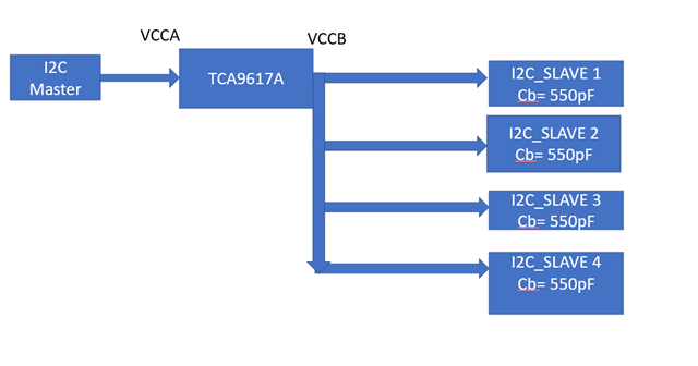
Can i use the TCA9617A in star connection as shown below. Each I2C slave with different address is working at 1MHz frequency. 

Pull ups are provided at each slave. Little bit afraid of loading caused by 4 slaves on one output of TCA9617A. 

Datasheet does say it can drive loads with 550pF or higher. What will be the max load it can drive for 1MHz ?

Thanks

ATharva

  • Hi Atharva,

    I see that you wrote Cb=550 pF for each device. Are you saying each of these devices have a bus capacitance of 550 pF? This would be way too high of a load for fast mode plus I2C operation. Since these devices are in parallel their capacitance would add up. The maximum load the TCA9617A can drive with fast mode plus (1MHz) is 550 pF.

    What is the input capacitance of each of these devices?

    Best,

    Chris

  • Hi Chris,

    Thanks for your revert. Yes wrote two different questions as doesn't want to confuse in our approach.

    So Slave I/o capacitance is 5pF each pin of I2C signal pins. Trace length around 10 inch.

    Total 4 slaves planned on one buffer. Assuming 3 pF/inch thumb rule.

    So i assume that accounts for total (5x4 = 20pF) + (10 inch x 3pF x 4 slaves  = 120pF) = 140 pF

    I guess, this 140pF bus capacitance is okay for buffer to drive 4 slaves at 1MHz.

    Can you confirm my calculation if possible ?

    Thanks

    ATharva

  • Hi Atharva,

    I can confirm your bus capacitance calculation but I just want to make sure. Is your overall topology that you will have multiple TCA9617 sensors, and attached to each sensor on the B side are 4 slave devices?

    Best,

    Chris

  • So current topology is one TCA9617 IC, 4 slaves connected to it.

    Slave device only supports 1MHz, hence was bit skeptical earlier.

    I2C white paper on buffers and your help on calculating PU resistance paper helped me clarify my doubt

    I was misjudging trace capacitance by large margin.

    Thanks

    Atharva

  • Got it, so with that current topology your bus capacitance calculation is correct.  The one difference is if the 5 pF for each I2C pin is 10 pF per device or just 5 pF for each device. Either way, since the total bus capacitance is so small it won't make a difference. For the pcb trace capacitance I've heard of estimations similar to that but it will all depend on the width of your trace.

    Since you have a lot of headroom for your maximum bus capacitance you won't have to worry about it.

    Best,

    Chris