This thread has been locked.

If you have a related question, please click the "Ask a related question" button in the top right corner. The newly created question will be automatically linked to this question.

THVD8000: THVD8000 CIRCUIT VERIFICATION

Part Number: THVD8000

Hello Hao,

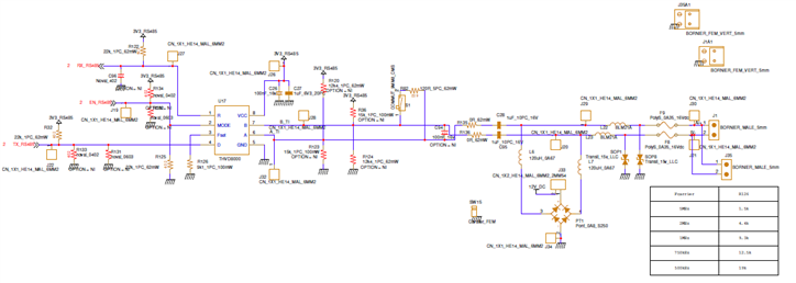
Could you please check my circuit connections to verify if it is correct for the THVD8000 chip in order to proceed to the PCB production?

Thank you in advance,

MO

  • MO,

    Is this board design for power transmitting or power receiving? In general the recectifier is needed at the receiver side if only the power polarity can change (Figure 9-1 in the datasheet). 

    You may also want to double check the grounding. The power ground and transceiver's ground are isolated. In other words, DC is blocked and data (AC) passes the decoupling capacitor. 

    The pull up/down resistors on bus may not be necessary. I put them on EVM for debugging.

    It looks like the design is 12VDC. Please be sure protection diodes refer to the proper ground. Also the decouple capacitor is rated 16V. It might be better to choose  higher voltage rating, since the supply might not be clean. 

  • Thank you Hao for the response.

    In fact, this circuit design refers for power receiving. 

    As illustrated in the first figure, the decoupling capacitor are in the right place, right?

    And for the protection diodes, are they placed in the correct place, i mean at the input of the board? Also, their connections to the ground might be fine as they are connected to the ground of the rectifier. 

    Thank you again

    MO 

  • The decoupling capacitor are in the right place. If you want to protect the IC, you may want to move the protection diodes from the bus side to the IC pin side. Then the grounding makes more sense.