


Part Number: TPD3S714-Q1
Hi Team,
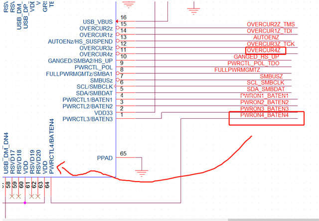
The USB protection chip TPD3S714-Q1 in Figure 1 is used in conjunction with TUSB4041, where /FLT is connected to the OVERCUR4Z pin of TUSB4041, and the EN pin is connected to BATEN4, as shown in Figure 2.
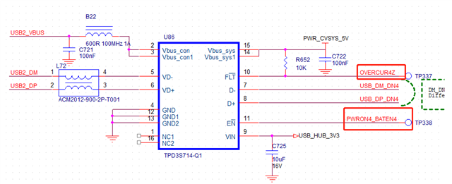
The current problem is that before the TPD3S714-Q1 is enabled, the oscilloscope is used to measure the /FLT pin and the display is 0V. After the TUSB4041 collects the state of this pin, it is considered to be faulty.
We suspect that the 4041 is detected as a fault state, and the TPD3S714-Q1 is not enabled to control the output, so the U disk cannot be accessed.
We tried to disconnect the 10-pin FLT of TPD3S714 from 4041 and found that the U disk can be used normally.
Is the chip application correct? How to solve this problem?
