Part Number: DP83TG720EVM-MC
Hi,
I was conducting PMA conformance tests for the DP83TG720R Media Converter board.
I consistently faced failures in PMA conformance tests in:
- master jitter
- slave jitter
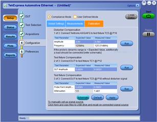
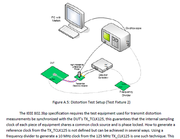
- Tx distortion
I have attached my test results.DP83TG720.zip
I have actually also check the test setup using other DUTs (from other manufacturers). I can get a pass results.
I have been using these test scripts file (see attachments) to set master and slave modes, and corresponding test modes.
begin

//Master Mode Configuration
//Hard reset
000D 001f
000E 001f
000D 401f
000E 8000

//to not let the phy start the link-up procedure
//( till full configuration is written)
000D 001f
000E 0573
000D 401f
000E 0101

//to configure phy in master mode
//(if not done through straps already)
000D 0001
000E 0834
000D 4001
000E c001

//DSP settings for margins during OA EMC MDI
//emission test
000D 001f
000E 0405
000D 401f
000E 5800

//DSP settings for margins during OA EMC
//level-4 immunity test
000D 001f
000E 08ad
000D 401f
000E 3c51

000D 001f
000E 0894
000D 401f
000E 5df7

000D 001f
000E 08A0
000D 401f
000E 09e7

000D 001f
000E 08c0
000D 401f
000E 4000

000D 001f
000E 0814
000D 401f
000E 4800

000D 001f
000E 080d
000D 401f
000E 2ebf

000D 001f
000E 08c1
000D 401f
000E 0b00

000D 001f
000E 087d
000D 401f
000E 0001

000D 001f
000E 082e
000D 401f
000E 0000

000D 001f
000E 0837
000D 401f
000E 00f4

000D 001f
000E 08be
000D 401f
000E 0200

000D 001f
000E 08c5
000D 401f
000E 4000

000D 001f
000E 08c7
000D 401f
000E 2000

000D 001f
000E 08b3
000D 401f
000E 005a

000D 001f
000E 08b4
000D 401f
000E 005a

000D 001f
000E 08b0
000D 401f
000E 0202

000D 001f
000E 08b5
000D 401f
000E 00ea

000D 001f
000E 08ba
000D 401f
000E 2828

000D 001f
000E 08bb
000D 401f
000E 6828

000D 001f
000E 08bc
000D 401f
000E 0028

000D 001f
000E 08bf
000D 401f
000E 0000

000D 001f
000E 08b1
000D 401f
000E 0014

000D 001f
000E 08b2
000D 401f
000E 0008

000D 001f
000E 08ec
000D 401f
000E 0000

000D 001f
000E 08c8
000D 401f
000E 0003

000D 001f
000E 08be
000D 401f
000E 0201

//to bring phy out of non-autonomous mode
//( only if phy is strapped in non-auto mode)
000D 001f
000E 018c
000D 401f
000E 0001

//soft reset
000D 001f
000E 001f
000D 401f
000E 4000

//to let phy start the link-up procedure
//(after above configuration is done)
000D 001f
000E 0573
000D 401f
000E 0001

//to start the send-s detection during link-up
//sequence
000D 001f
000E 056a
000D 401f
000E 5f41

end
begin

//Master Mode Configuration
//Hard reset
000D 001f
000E 001f
000D 401f
000E 8000

//to not let the phy start the link-up procedure
//( till full configuration is written)
000D 001f
000E 0573
000D 401f
000E 0101

//to configure phy in slave mode
//(if not done through straps already)
000D 0001
000E 0834
000D 4001
000E 8001

//DSP settings for margins during OA EMC MDI
//emission test
000D 001f
000E 0894
000D 401f
000E 5df7

//DSP settings for margins during OA EMC
//level-4 immunity test
000D 001f
000E 056a
000D 401f
000E 5f40

000D 001f
000E 0405
000D 401f
000E 5800

000D 001f
000E 08ad
000D 401f
000E 3c51

000D 001f
000E 0894
000D 401f
000E 5df7

000D 001f
000E 08a0
000D 401f
000E 09e7

000D 001f
000E 08c0
000D 401f
000E 4000

000D 001f
000E 0814
000D 401f
000E 4800

000D 001f
000E 080d
000D 401f
000E 2ebf

000D 001f
000E 08c1
000D 401f
000E 0b00

000D 001f
000E 087d
000D 401f
000E 0001

000D 001f
000E 082e
000D 401f
000E 0000

000D 001f
000E 0837
000D 401f
000E 00f4

000D 001f
000E 08be
000D 401f
000E 0200

000D 001f
000E 08c5
000D 401f
000E 4000

000D 001f
000E 08c7
000D 401f
000E 2000

000D 001f
000E 08b3
000D 401f
000E 005a

000D 001f
000E 08b4
000D 401f
000E 005a

000D 001f
000E 08b0
000D 401f
000E 0202

000D 001f
000E 08b5
000D 401f
000E 00ea

000D 001f
000E 08ba
000D 401f
000E 2828

000D 001f
000E 08bb
000D 401f
000E 6828

000D 001f
000E 08bc
000D 401f
000E 0028

000D 001f
000E 08bf
000D 401f
000E 0000

000D 001f
000E 08b1
000D 401f
000E 0014

000D 001f
000E 08b2
000D 401f
000E 0008

000D 001f
000E 08ec
000D 401f
000E 0000

000D 001f
000E 08c8
000D 401f
000E 0003

000D 001f
000E 08be
000D 401f
000E 0201

//to avoid send-s detection till the configuration is
//done
000D 001f
000E 056a
000D 401f
000E 5f40

//to bring phy out of non-autonomous mode
//( only if phy is strapped in non-auto mode)
000D 001f
000E 018c
000D 401f
000E 0001

//soft reset
000D 001f
000E 001f
000D 401f
000E 4000

//to let phy start the link-up procedure
//(after above configuration is done)
000D 001f
000E 0573
000D 401f
000E 0001

//to start the send-s detection during link-up
//sequence
000D 001f
000E 056a
000D 401f
000E 5f41

end
begin
//100BASE-T1 PMA Test Control Register
// enabling test mode 1
000D 0001
000E 0904
000D 4001
000E 2000
//Read
000D 0001
000E 0904
000D 4001
000E
end
begin
//1000BASE-T1 PMA Test Control Register
// enabling test mode 4
000D 0001
000E 0904
000D 4001
000E 8000
000D 001F
000E 0453
000D 401F
000E 0019
//Read
000D 0001
000E 0904
000D 4001
000E
000D 001F
000E 0453
000D 401F
000E
end
Is there any possible configurations required? Or the DP83TG720R media converter is a suitable candidate to perform these tests?
Please help.