This thread has been locked.

If you have a related question, please click the "Ask a related question" button in the top right corner. The newly created question will be automatically linked to this question.

TCAN1043H-Q1: CAN Transceiver blew, unknown root cause

Part Number: TCAN1043H-Q1
Other Parts Discussed in Thread: TCAN1043

Hi there, 

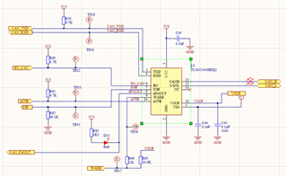
My team is using the TCAN1043HDQ1 in one of our PCBs. We had this PCB hooked up to a larger system. While the PCB was powered off, meaning all VCC/VSUP/VIO/GND pins were unconnected, the rest of the system was being tested, meaning CAN messages were being sent. 

When the PCB was powered back up, the CAN chip had blown and needed to be replaced. No other part of the circuit was damaged, which leads me to believe it was not an issue with power, as there are dozens of other chips on the board running off the same power/ground rails. 

I am looking for any suggestions on possible failure modes in this configuration that could have caused this issue. 

Thank you

  • Hi Katie,

    Can you specify how you know the CAN chip had blown. What tests were preformed to make sure it doesn't work anymore?

    Can you also send any scope shots of the system powering on (VCC, VSUP,VIO and EN). Specifically I want to see how the voltage ramps from 0V to it's operating voltage and if there are any crazy ripples or faults.

    Also while the PCB was turned off was the CAN bus still connected to the larger system that was being tested. If that is the case then what voltages is your CAN bus running at?

    Lastly if you can send a schematic of your TCAN1043 and what components are connected to it that would be great.

    Best,

    Chris

  • We knew the CAN chip didn't work anymore because the board was powering on and we could communicate with it over separate communication interfaces, but not CAN. We replaced the chip and the board was back to full functionality. 

    I don't have any scope shots unfortunately, if those become critical I can get some, but the unit is back in use at the moment 

    The CAN bus was running at 5V nominal 

    This is how the CAN bus is connected, where WAKE is external and normally unconnected, and all other signals connect to a microcontroller running at 3.3V logic levels. VBat was at around 48V. 

  • Katie,

    Thanks for all of this information. Another measurement that will help pinpoint the damage is checking the impedance of each pin to GND on the damaged device and comparing it to the known good device. If this is the result of electrical overstress, we should see a short (or very low impedance) to GND on the damaged pin.

    Oscilloscope screenshots of the power-up waveforms, as well as the CANH and CANL pins during normal operation will help as well. 

    Regards,

    Eric Hackett