This thread has been locked.

If you have a related question, please click the "Ask a related question" button in the top right corner. The newly created question will be automatically linked to this question.

TPS65986: Can't connect using TPS65986EVM

Part Number: TPS65986

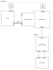
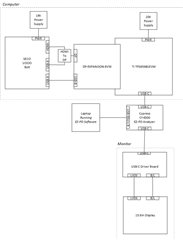
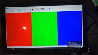
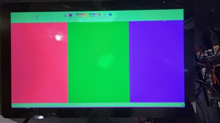
I am trying to use the TPS65986EVM to connect to a USB-C display driver board that has a Realtek RTD2778R USB-C chip.  I have an UDOO (SECO) SBC with USB-C out.  When I connect the USB-C of the SBC directly to my USB-C board, it works correctly.  I then disconnect the USB-C cable between the SBC and the USB-C board.  I then connect the TPS65986EVM board to the SBC using the supplied USB-B cable.  I am powering the TPS65986EVM using a Dell 20V laptop supply as specified.  Then I connect the USB-C cable between the TPS65986EVM and the USB-C display board.  As soon as I connect the USB-C cable, the LED's on the TPS65986EVM begin to blink rapidly and my display does not turn on.  I used a Cypress CY4500 USB-C protocol analyzer to monitor the USB-C messages when connected directly to the SBC and when connected via the TPS65986EVM.  When connected directly, I get a long set of USB-C messages on the protocol analyzer.  When I connect through the TPS65986EVM, I get no messages on the analyzer.

I have not modified the TPS65986EVM in away way.  The firmware has not been updated and the DIP switches are all at 0.

  • Hi Tony,

    If there are no PD messages showing up, the EVM may not have been configured or programmed and I think the two devices might not have matching capabilities. Also, I noticed you said you connected the EVM via a USB-B cable, I'm guessing this is just a typo correct?

    Could you please share a block diagram here showing your board and how you are testing?

    Thank you,

    Hari

  • The TI TPS65986EVM board is connected to the SBC via a USB-B Super Speed cable.  A block diagram is atatched.

  • Hi Tony,

    I see you're using the DP-Expansion board, do you see the HPD signal go high? 

    Also, for the EVM, could you please scope VIN_3V3 and LDO_3V3 and let me know if you see those signals correctly without the Type-C cable plugged in? 

    Have you verified the setup section of the EVM User's Guide that the settings for DP are matching?

    Thank you,

    Hari

  • The HPD signal does not go high.  I measured VIN_3V3 at C17 and I believe it's 0V.  C17 is tiny so I'm not positive that I wasn't making a good connection, and I can't find anywhere else to measure VIN_3V3.  I measured LDO_3V3 at multiple locations and all of them were around 200mV.  I read through the manual and I believe the default board settings and firmware are what I want, but I'm not a USB-C expert so I could be wrong.  My ultimate goal is to use the expansion board to provide atl mode DP signals though the USB-C, but for now I don't have the DP cable connected.  I'm just trying to get the USB-C connection established first.  I'm also not sure why I need the high speed USB-B connection to the expansion board or if the host side of the USB-B needs to be anything special.  I think the USB connection I'm using for that on the SBC is a standard USB 2.0 port.  Is that a problem?

  • I also tried to use the TPS6598x Utilities to check the board setup, but I could not get it to work.  I'm using Win 10.  The Device Manager shows an "Atmel USB Devices->TPS65982" with an explanation point on it, and the FTDI drivers show up in the "Universal Serial Bus Controllers" as "Unknown USB Device...".  I tried reinstalling the FTDI drivers using their specific driver utility.  I also tried both the 32-bit and the 64-bit version of the utilities.  Neither worked.  And I don't have an Aardvark.

  • I read through the manual again and I think I might have had the DIP switches set incorrectly due a confusion between DFP and UFP.  I originally had them at 0000 which would be config 1 and default to UFP.  But then I saw the example in the manual showing two EVM's connected together with one sourcing the DP signal (Table 11).  The guide says that EVM should be set to 1000 which is config 1 default to DFP.  That config shows sinking 20V but I want to source 20V, so I tried 0100 config 2 which is DFP and sourcing 20V.  I got the same behavior.

  • Hi Tony,

    If you are not seeing VIN_3V3 or LDO_3V3 on the board then that's likely the issue as the device may trying to boot in dead battery mode, regardless of the DIP switch configuration. Since, you are sourcing, you will need to provide power to the device and have the 20V on PPHV ready to source that contract.

    Also, is there a reason you are using the TPS65986 in your design? This device is outdated and I would recommend using the TPS65987DDH. Please take a look at the datasheet of that device and it will have a section for typical applications where it shows a block diagram of the device along with other devices that are needed for DisplayPort functionality.

    Additionally, to become more familiar with USB Type-C and PD, I would recommend watching these tutorial videos: 

    https://training.ti.com/how-evaluate-and-configure-our-usb-type-c-pd-controllers

    For the TPS65982 EVM, the tool that you will allow you to program your personal configurations is this one not the utilities: https://www.ti.com/tool/TPS6598X-CONFIG

    Thank you,

    Hari

  • 'm not planning on using the TPS65986 in my design.  I'm just trying to use the EVM to test this USB-C board I have.  I don't understand what you mean about providing power to the device.  If you mean my USB-C board which is acting as a UFP, then I don't have any way to provide power to that board except through the USB-C cable.  That was the whole point of our USB-C board.  A customer can use it to drive a monitor and only need a SUB-C cable without any additional power.

  • Hi Tony,

    Sorry, I meant that the PD Controller TPS65986 should be getting power and to confirm this, you will see VIN_3V3 and LDO_3V3 are both at 3.3V. Are you able to see this? If not, this will prevent the PD controller to configure correctly. For the USB-C board for the display, yes that's correct, you should be able to configure it such that the Type-C cable can provide the power to the board and sink power.

    Thank you,

    Hari

  • I ordered a second TPS65986EVM board which arrived today.  I tested both boards (my original TPS65986EVM and the new one) by connecting them to my laptop.  I connected the USB-B high speed cable to the expansion board and a USB-A to USB-C to the TPS65986EVM board.  Both boards came up with a steady light pattern on the LEDs.  I measured VIN and LDO and they were good (3.3V and 1.8V).  I then put one of the boards into my system connected as I had shown in the previous system diagram.  The TPS65986EVM and expansion board are connected to my SBC via the high speed USB-B cable.  The USB-C connector on the TPS65986EVM is connected to my USB-C board.  The TPS65986EVM board is powered by a 20V laptop supply.  The DP cable is not connected.

    The LEDs on the TPS65986EVM blink on and off rapidly.  I measured the VIN and LDO and they were both good (3.3V and 1.8V).  I must not have had made good contact the last time I measured them.  I then checked VBUS and saw it constantly going to 5V and then back down again.  I'm including screen shots showing VBUS over 500ms, 10ms, and 2.5ms.  I also used the Cypress CY4500 USB-C analyzer to monitor the messages between the TPS65986EVM and my board.  No messages were sent.

    So apparently the TPS65986EVM board is powered up, but it will not provide consistent 5V to my USB-C board.  I don't think this is a PD negotiation issue since I don't see any messages with the analyzer.  I'm not sure what to look at next.  Any suggestions?

  • Hi Tony,

    Let me look into this and I will provide feedback later this week.

    Thank you,

    Hari

  • Hi Tony,

    I would recommend programming the TPS65986EVM using the GUI tool from the EVM product page so this way you can configure the PD controller exactly the way the design requires.

    For the VBUS issue, could you check the different boards and make sure there aren't other devices connected to the VBUS of the TPS65986 which could be showing this behavior. I would also recommend scoping both of the CC pins to see how they are behaving.

    Thank you,

    Hari

  • We figured out the voltage issue.  Our USB-C board was programmed to use 5V, 9V, 15V, and 20V.  Apparently that is an issue since the TPS65986EVM is setup to only support 5V and 20V.  We reprogrammed our USB-C board to support only 5V and 20V and we were able to get the voltage to stabilize at 20V.   But then I got to our real problem: the DisplayPort on the TI board isn't working.  

    First I reloaded our USB-C board with the 5V-9V-15V-20V firmware.  Then I purchased a TPS65981EVM which also supports all those voltages.  I also purchased a Cypress CY4500 PD analyzer.  I connected everything as shown in the attached block diagram.  I then looked at the message log from the EZ-PD analyzer.  I found that the TI board asks what modes are supported, and our USB-C board replies that DisplayPort mode is supported, but the TI board never requests to enter DisplayPort mode.  So the issue seems to be that the TI board isn't sending the DisplayPort signals.

    We are supposed to deliver our demo to our customer in 2 days.  I live in Dallas.  Is there a local TI FAE I can work with on this?

  • Hi Tony,

    The TPS65981/6 devices are a little older, if your design is not set, I would recommend using the TPS65987DDH in the design for DisplayPort, also since the DP Expansion boards are not supported anymore. Please take a look at the DisplayPort Alternate Mode app note that we have here: https://www.ti.com/lit/pdf/slva844

    There are a few different reasons that the PD controller may not be sending the Enter Mode message, in the app note there is a debugging section that should help here. Could you please upload the PD log here? 

    This app note along with the TPS65987D datasheet's typical application will demonstrate how the device can be used in an application for DisplayPort support.

    I will look into seeing if there is a local FAE that could support you.

    Thank you,

    Hari

  • Please note the TPS65987DDH is not in stock and is reporting a 53 week lead time.  I don't know about your schedule, but I can't wait that long.

  • I'm attaching an Excel version of the PD log.  I also tried to upload the native file which has more details for each message, but the post interface apparently won't let me upload unrecognized file extensions.  I'm also attaching a log for an example where I connect directly to our USB-C board without the TI TPS65981EVM which works.  So I know our USB-C board will take DP in over USB-C if the host offers it.

    I also did a test where I connected the DP output to a monitor to confirm that my HDMI-to-DP converter is working.  That worked as expected.  So I'm positive that I'm putting DP signals into the TI expansion board.

    I also tried to connect to the TPS65981EVM using the TPS Application Customization Tool, but I can't get that working either.  The TPS65986EVM manual doesn't say anything about the add-on board that is connected to the TPS65981EVM, but based on another post response I saw, I believe the second board which is attached breakaway-style is an FTDI converter board.  I can see traces running between the boards on the small breakaway tabs, so I assume I can just connect to the USB micro-B connector on the FTDI board to connect to the TPS6981EVM board.  But when I try that the TPS Application Customization Tool can't find the board.  I tried the "Sweep I2C address range for device response".  It apparently doesn't find the board.  I say "apparently" because it doesn't say one way or the other.  It just widens the dialog box to be about 3 times my screen size and shows all the available I2C addresses from 0 to 0x7F.  When I try the three "Test..." options underneath that, the first two report nothing and the third says "Ready", but I don't believe it based on everything else I have tried.

    FYI, we don't plan on using the TPS65981 in our design.  For now I'm just trying to prove that the TI chips are compatible with our USB-C board so I can tell our customers to use the TI USB-C chips in their designs.

    5V FW with SECO DP Working.xlsx5V-9V-15V-20V FW with TPS65981EVM No DP Connected.xlsx

  • One more general comment: at this point I've spent over $2500 on various TI eval boards and add-ons.  I'm getting very frustrated that I can't get this to work and I can't get an FAE to contact me directly, even though the main TI campus is about 10 miles from my office.

  • After reviewing he TPS65981EVM user's guide again, I think the issue is that it doesn't natively support the combination of features I'm trying to use.  My goal is to use the TPS65981EVM to source 20V at 3A to my USB-C board, and to use the TPS65981EVM to source the DP signal through USB-C to my board.  After studying the firmware configurations table in section 6.2 of the user's guide, and noting the switch positions given in the example setup in section 6.3.4, it looks like when you configure the TPS65981EVM to source all the available voltages (CFG ID 0), it can act as a UFP_D meaning, if I understand the terms correctly, it can only receive a DP signal, not source it.  If you configure it to be a DFP_D, meaning it can source a DP signal, then it only supports 5V as a source voltage.  Is my understanding correct?

    If that is correct, then my next question is: can I configure the TPS65981EVM to source 20V AND be a DFP_D by using the TPS Application Customization Tool to manually configure the TPS65981 chip?  Does the chip support that combination?  If so, then I need to get the TPS Configuration tool working.  If I can't get support on getting the FTDI board to program the TPS65981 chip, then I will order an Aardvark and see if I can use that.  But before I order an Aardvark, I would like to have confirmation that the TPS65981EVM can be configured to source both 20V and a DP signal.

  • Tony,

    Hari is out of office, please expect some delays on this. Please refer to this application note on configuration the DP alternate mode. https://www.ti.com/lit/pdf/slva844 . Application configuration should be able to do the DP source at 20V.

    For FTDI issues please search E2E on FTDI issues, there are several  threads how people solved their issues, you might find a relevant one to the issue you are facing. Typically, FTDI drivers can be a bit tricky. 

  • Thanks for letting me know about Hari.  I finally got my DP working about an hour ago.  I ordered an Aardvark and used it to change the DP setting in the TPS65981 from UFP_D to DFP_D while sourcing 20V.  My next problem is how to make that permanent, if I even can make a permanent change with the EVM.  The confusing thing is that the EVM has a bank of DIP switches which define it's operation (UFP, DFP, DRP, voltage sinking or sourcing, etc.).  It's not clear if I can change the TPS65981 to essentially ignore those DIP switches and only do what I tell it to.  If I change the configuration using the GUI, do I need to remove some resistors or something to keep the DIP switches from overriding my changes?  And how do I write my changes into the Flash of the TPS65981?  Right now I'm using the Debug mode in the GUI to change the settings, but there's no obvious "Write to Flash" option.  I do see options to create a new firmware which I assume I could then load, but I'm hesitant to start trying things like that without clear directions.  I can't afford to brick the TPS6591EVM since I only have one.

  • Tony,

    Once you change the configuration and Flash it, that will be the one used after reboot and it will override the default FW that was in the Flash.

  • Tony:  I agree with Ghouse's reply above.  I was able to get my DP intermittently working, but only if the connector is upside-up.  Can you share your project file?

  • My question is HOW do I Flash the changes?  There is not "Flash" command in any of the debug menus that I can find.  And I also don't know if any changes I make will be overridden by the DIP switch options.

  • Tony:  Exit debug mode, update the configuration under Port Settings, then go to Binary>>Flash From Current Project.  You need to have the SPI signals on the Aardvark connected to the EEPROM.  The TPS6598x does not act as a I2C to SPI bridge.  Once you have a working binary, you can use the Save Binary command to generate a file that you can give to a programming vendor.

  • I was able to program the TPS65981EVM following your instructions and it worked.  I tried programming a second TPS65987EVM and for some reason it is not behaving the same.  When I power it up and connect it, it constantly resets as if it can't negotiate a power contract.  When I use the Aardvark to check the settings, everything is correct.  If I reload the EVM firmware and change the DFP option, it works.  Not sure why programming it causes a problem.  I'll keep working on that.

    In the meantime, I have a new problem now that I have the DP_DFP_D setup.  There is a strange color shift on the display.  I created a JPG with pure RGB stripes and displayed it when connected directly to my SBC and when going through the TPS65981EVM.  The pictures are attached. 


    I know the display is OK because when connected directly to the SECO SBC via USB-C, the color is fine.  For the TPS65981EVM test I have an HDMI-to-DP converter connected to an HDMI output on the SECO.  I connected the DP end of the cable directly to another monitor that supports DP and the color was fine, so I know that the HDMI coming out of the SBC is correct, and I know the color is not affected by the HDMI-to-DP converter.  It appears that the TPS65981EVM is somehow causing this color shift.  Any idea what's causing this?