A related question is a question created from another question. When the related question is created, it will be automatically linked to the original question.
If you have a related question, please click the "Ask a related question" button in the top right corner. The newly created question will be automatically linked to this question.
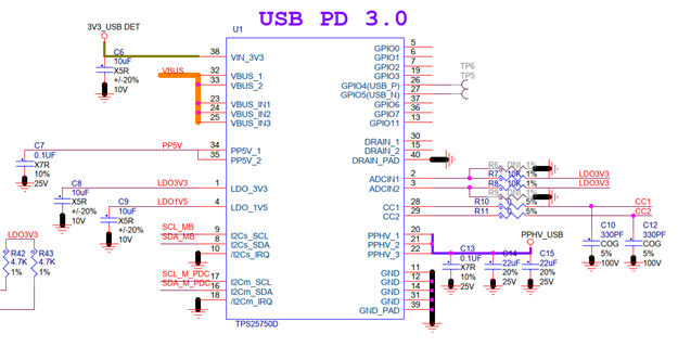
Please add pull up resistors to I2Cs_IRQ and I2Cm_IRA. This will prevent them from generating interrupts during bootup.
Connect 30, 15, 40 (DRAIN) together, but DO NOT connect them to any other signal. This will cause the part to fail
Make sure that the I2Cm_SCL and I2Cm_SDA pins are pulled high with 4.7 K resistors and connected to the SCL and SDA pins of the charger. The charger connection is not connected correctly. The I2Cs_SCL and I2Cs_SDA pins should be connected to the CPU/MCU. They should also be pulled up to LDO_3V3 through a 4.7k resistors.
The TPS25750 has commands that will allow the CPU to access all of the BQ24792 registers from the I2Cs bus.
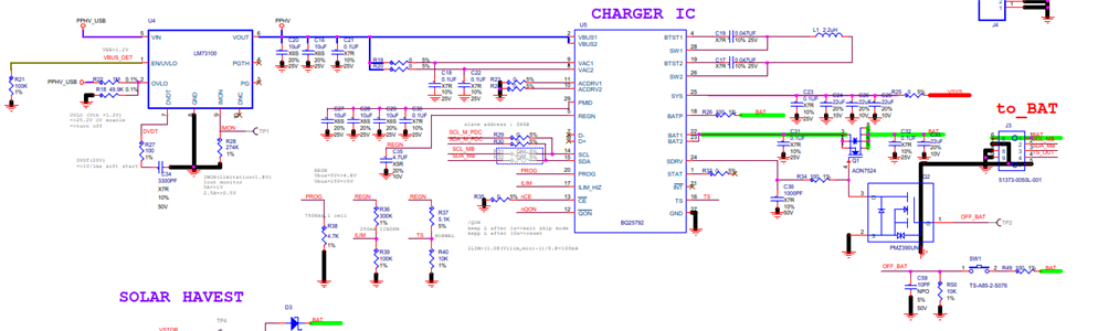
If you would like me to assign this to the BQ charger team to review the BQ schematic, I am happy to pass it along.