This thread has been locked.

If you have a related question, please click the "Ask a related question" button in the top right corner. The newly created question will be automatically linked to this question.

TPS25750: question about I2C address setting

Part Number: TPS25750


Dear Team,

1.How do I set the I2C address? Is there only the following four options?

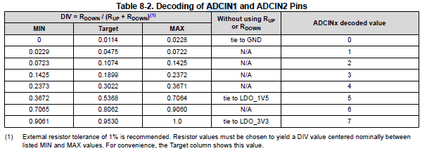
2.Table 9-5, Could you guide us how to  using ADCIN1 and ADCIN2 to configuration device. Thanks a lot!

3. Can we use I2C to read the polarity (directivity) of USB?

Many Thanks,

Jimmy

  • Jimmy,

    1.  There are only 4 possible I2C addresses

    2. Here is a graphic of the ADCIN1 and ADCIN2 voltage to achieve the ADCIN decodes

    3.  Yes you can read the connection polarity from I2C.  There is also a GPIO mapping for this feature if you need it.  The I2C interface is described in the Host Interface Manual:  TPS25750 Host Interface Technical Reference Manual

  • Hi Sirs,

    Could you please help to reply the questions in the screenshot photo?

    I want to configure the TPS25750D via the I2Cs interface, but I'm not sure the unique address in the I2C protcol, which was shown in the mannul.

    If not what i asked in the photo, what are the unique address really,and where can be found?

    Thanks,

    Matt,

  • The unique address is defined the first datasheet table you are sharing. It is set from ADIN1 and ADCIN2 resistor divider setting.

    It can take 1 of 4 I2C addresses. 0x20, 0x21, 0x22 or 0x23. 

    I think you are confusing the Register address with Unique I2C address for the part/port.

  • Hello Ghouse,

    Thank you very much for your reply.

    -  You mean the Slave address, maybe one of #1,#2,#3,#4 which was configured from ADCIN1&ADCIN2, is the Unique address?

       So, the address in the register table(2-1) are the register numbers(Table 1-1). 

     -   It can take 1 of 4 I2C addresses. 0x20, 0x21, 0x22 or 0x23. Seems ignored the bit0(W/R)? For the bit0 cannot be sure from datasheet view, which decided by the actual condition.

    - The table below, where can be looked for? I cannot find in the datasheet and  also the technical reference mannal,but it's really       importatnt and necessary for developers.

    That's why I'm confused on the actual slave address, as well as the unique adress. If have no these data, we really don't know how to configure, what the meannign of the decoded value mean, for there are 3 teams of configuration:

    Thanks,

    Best Regards,

    Matt

  • Matt,

    IF you work example. Say ADCIN1=7 and ADCIN2 = 3 and you see from the table that the I2C address is #1 = 0x20.

  •  Hello Ghouse,

    Thanks, understood.

    - So, here Bit0 included in slave address is not proper, that maybe lead some users wondering, for the protcol slave address is 7bit.

    The table 8-2 bellow is rather the key information for users' software devoleping. If only know the decoded value, we actually don't know how to configure.  I think most of the users prefer to configure the PD controller via an emdedded MCU than the GUI tool in the future. So i suggest to upload these documents are rather necessary. Actully, i am rather interesting this document. I think it can resolve lots of qustions for me.Relaxed

    - Another question, Does all 4 slave addresses can be selected by customers via configuring ADCIN1&ADCIN2? For in the technical reference mannul only mentioned that "Slave Address #1 is selected by the customer using the ADCIN1 and ADCIN2 pins on the PD controller." , mean #2, #3, #4 cannot be selected by customer? That makes me rather wondering for there are no other information for 2#, 3#, 4# slave address in datasheet and technical mannul. They only listed the decoded values.

    Thanks,

    Best Regards,

    Matt

  • Possible to select all the slave address for I2C1. There is a corresponding I2C2 address typically, but it could get overwritten by the Application configuration GUI after the boot has happened.