This thread has been locked.

If you have a related question, please click the "Ask a related question" button in the top right corner. The newly created question will be automatically linked to this question.

TCAN4550: TCAN4550 SPI to CANFD in TMDX570LC43HDK Polling method or interrupt method

Part Number: TCAN4550
Other Parts Discussed in Thread: TMS570LC4357, , MSP430FR6989, TMS570LS1224,

Hi Teams,

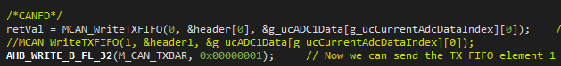
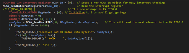
I need a support for TCAN4550 BOOSTXL - CANFD-LIN  configuration to Transmit and receive CANFD with TMS570LC4357.

The interrupt method is working fine in Launchpad but I need to checking with polling method or interrupt method with only nINT pin for my custom board.

nINT  -- GIOB[6]

CAN_RST -- N2HET1[11]

SPI3_NCS0

SPI3_SIMO

SPI3_SOMI

SPI3_CLK


Is it must to use the CAN_GPIO1_INT and CAN_GPIO2_INT in TCAN4550 ?

GIOA[0] - CAN_GPIO1_INT and GIOA[1] - CAN_GPIO2_INT

Any example code for TMS570LCx MCU for polling method without using nINT. 

and interrupt method using only nINT not CAN_GPIO1_INT and CAN_GPIO2_INT in TCAN4550?

Thanks in advance.

  • Hi Santhosh, 

    The TCAN4550 has a dedicated interrupt pin (pin 8, nINT) that reflects the state of the global interrupt status flag. The interrupts that can be configured for GPIO1 and GPO2 are constrained to specific interrupt statuses and thus cannot be used for general purpose interrupt detection. 

    For an example of how an interrupt based method can be used, I'd encourage the review of the TCAN4550 DEMO software written for MSP430FR6989 found on the device store page. The main.c file here has an interrupt vector defined to run every time the nINT signal transitions from high to low, indicating an interrupt is being signaled by TCAN4550. This can wake the MCU so it may begin to identify and service the interrupt. 

    Let me know if you have questions on this demo or the nINT function of TCAN4550. 

    Regards,
    Eric Schott

  • HI Eric Schott1,

    I have review and used the TMS570LS1224_TCAN4550_Demo_Node1 code and checked the Transmit the CANFD signal it worked properly, But I couldn't get the reception signals for multiple signals as 

    Transmit 

    Please help me on Polling method for init setting and transmission and reception CAN signals.

    MCAN_WriteTXFIFO function is used as polling method the argument is fifoNumber is it 0 to 32 n ?

    In the above code I have used FIFOnumber is 0 and 1 So the 

     AHB_WRITE_B_FL_32(M_CAN_TXBAR, 0x00000003);  

    0x00000003 is the bit 0 and bit 1 is transmitting signal  is it correct ?

    How to receive the multiple CAN signals 

    Here I have used only RXFIFO as 0 alone for all message I couldn't read properly and  read the signals .

    TCAN45x_Init.c file Here the m_can_int1 is enabled it means GPO2 is selected interrupt. 

    and what is the purpose of SFID1 which act as filter the CAN signal as per the below picture is 0x158 then I can only given signals as 0x148 , 0x118, 0x140, 0x110,0x048, 0x040 but the signals should not be 0x284 and 0x424 is it correct ?

    I couldn't read this CAN signals 0x284 and 0x424 is it correct ?


    Thanks in advance.

    Please reply as soon as possible.

  • Hi Eric, 

    I am getting an compiler error for identifier "header" is undefined but it is defined.

    TCAN45x0_TX_HEADER  is defined struct in TCAN45x.h this file is included 

    In reception CAN signal, multiple CAN signal is not coming properly from RXFIFO Buffer 0 and Buffer 1. 

    How to shift the FIFO for the next RXFIFO read in TCAN4550 using TMS570LC4357.

    Please help me to fix this issue.

  • Santhosh,

    I just wanted to give you an update and let you know we are looking into this and will reply after the weekend on Monday. Thank you for your patience.

    Regards,

    Eric Hackett

  • Hi ,

    I need to configure the TCAN45x_devConfig function as per the custom board.

    TCAN45x_devConfig
    LAUNCHPAD
    MCU TCAN45x board
    GPIOA -- bit0 -- nINT
    GPIOA -- bit1 -- GPO2
    GPIOA -- bit7 -- GPIO1
    GPIOB -- bit3 -- GPIO RESET
    SPI3 -- nCS_2 -- nCS_0

    I have configured the code please check and confirm but it is not working.

    CUSTOM BOARD
    MCU TCAN45x board
    GPIOA -- XX -- nINT
    GPIOA -- XX -- GPO2
    GPIOB -- bit-- GPIO1
    N2HET1 -- bit-- GPIO RESET
    SPI3 -- nCS_0 -- nCS_0

    I have configured the code as per the custom board But Still it is not working 

    please check and confirm me as soon as possible.

    Thanks in advance.

  • Hi ,

    I have tried this configuration for GIOA[0] for nINT [TCAN45x] and GIOB[6] for GPIO1 [TCAN45x]

    if I change the GPIO1 to GIOB[6] than it is not working but it working with GIOA[7] but in same configuration as GIOB[6] in software.

    Anywhere in the code is it hardcoded for GIOA[7] other than TCAN45x_devConfig function ?

    hw_config.h file has some define for 

    /**/
    #define CAN_nINT_PIN                GIOA0
    #define CAN_GPIO2_PIN             GIOA1
    #define CAN_nWRKQ_PIN           GIOA2
    #define CAN_GPIO1_PIN             GIOB6 //GIOA7
    #define CAN_RST                         GIOB3

    but this definition is not used anywhere in the code.

    void TCAN45x_devConfig()
    {
        gioPORTA->DIR     = (uint32)((uint32)0U << 0U);     /* Bit 0/1/2/7 */
        gioREG->POL       = (uint32)((uint32)0x0U << 0U);   /* Bit 0/1, falling edge */
        gioREG->LVLSET    = (uint32)((uint32)(0x01|0x4000));   /* GIOA Bit 0/1/2/7, GIOB Bit 2, high priority interrupt */
        gioPORTA->PULDIS  = 0x01; /* Bit 0/1/2/7, disable the pull */
        gioPORTB->PULDIS  = 0x40; /* Bit 2, disable the pull */
        gioEnableNotification(gioPORTA, 0x01); //enable the INT on GIOA0,GIOA1,GIOA2,GIOA7
        gioEnableNotification(gioPORTB, 0x40); //enable the INT on GIOB2, user button input
    }
    

  • Hi ,

    How to make multiple of transmit CANFD and multiple reception signals.

    If the transmit is 2 then I need to change the M_CAN_TXBAR 3 from 1 ?

    AHB_WRITE_B_FL_32(M_CAN_TXBAR, 0x0000000003); 

    Similarly how to read multiple of reception CANFD signals using MCAN_ReadNextFIFO ?

            if(1)
    		{
                MCAN_WriteTXFIFO(0, &header1, &g_ucADC1Data[g_ucCurrentAdcDataIndex][0]);  
                AHB_WRITE_B_FL_32(M_CAN_TXBAR, 0x0000000001);
    		}
    			TCAN45x0_CAN_Interrupt_Register MCAN_IR = {0};  // Setup a new MCAN IR object for easy interrupt checking
                MCAN_ReadInterruptRegister(&MCAN_IR);           // Read the interrupt register
                //if (MCAN_IR.RF0N) {                     // If a new message in RX FIFO 0
                    TCAN45x0_RX_HEADER MsgHeader = {0}; // Initialize to 0 or you'll get garbage
                    uint8_t numBytes = 0;
                    uint8_t dataPayload[64] = {0};
                    numBytes = MCAN_ReadNextFIFO( 0, &MsgHeader, dataPayload);    // This will read the next element in the RX FIFO 0
    				if (MsgHeader.ID == 0x148)
    				{ 
    					TMS570_DEBUGF(("Received CAN-FD Data: 0x%x bytes\n", numBytes));
    					for(i=0; i<numBytes; i++){
    						TMS570_DEBUGF(("  0x%X     ", dataPayload[i]));
    					}
    					TMS570_DEBUGF(("  \n\n "));
    				}
    

    Thanks in advance.

  • Hi ,

    How to make multiple of transmit CANFD and multiple reception signals.

    If the transmit is 2 then I need to change the M_CAN_TXBAR 3 from 1 ?

    AHB_WRITE_B_FL_32(M_CAN_TXBAR, 0x0000000003); 

    Similarly how to read multiple of reception CANFD signals using MCAN_ReadNextFIFO ?

    TCAN45x0_CAN_Interrupt_Register MCAN_IR = {0};  // Setup a new MCAN IR object for easy interrupt checking
                MCAN_ReadInterruptRegister(&MCAN_IR);           // Read the interrupt register
                //if (MCAN_IR.RF0N) {                     // If a new message in RX FIFO 0
                    TCAN45x0_RX_HEADER MsgHeader = {0}; // Initialize to 0 or you'll get garbage
                    uint8_t numBytes = 0;
                    uint8_t dataPayload[64] = {0};
                    numBytes = MCAN_ReadNextFIFO( 0, &MsgHeader, dataPayload);    // This will read the next element in the RX FIFO 0
    				if (MsgHeader.ID == 0x148)
    				{ 
    					TMS570_DEBUGF(("Received CAN-FD Data: 0x%x bytes\n", numBytes));
    					for(i=0; i<numBytes; i++){
    						TMS570_DEBUGF(("  0x%X     ", dataPayload[i]));
    					}
    					TMS570_DEBUGF(("  \n\n "));
    				}

    Thanks in advance.

  • Hi ,

    I have doubt in only RX FIFO and RX buffer to read multiple CAN FD signal using RXFIFO 0 and RXFIFO 1.

    and I couldn't able to read the RXF1S register for the FIFO at index 

    I have shared my code below please check it and let me know and how to modify for multiple CANFD signal read.

    config_value_type_t CFGTYP;
    CFGTYP = CurrentValue;
    TCAN45x0_Device_config_reg_t DEV_REG = {0};
    MCAN_GetDevConfigValue(&DEV_REG, CFGTYP);
    TCAN45x0_MCAN_config_reg_t MCAN_REG ={0};
    MCAN_GetMRAMConfigValue(&MCAN_REG, CFGTYP);
    TCAN45x0_CAN_Interrupt_Register MCAN_IR = {0};  // Setup a new MCAN IR object for easy interrupt checking
    MCAN_ReadInterruptRegister(&MCAN_IR);           // Read the interrupt register
    if (MCAN_IR.RF0N) {                     // If a new message in RX FIFO 0
     TCAN45x0_RX_HEADER MsgHeader = {0}; // Initialize to 0 or you'll get garbage
     TCAN45x0_RX_HEADER MsgHeader1 = {0}; // Initialize to 0 or you'll get garbage
     uint8_t numBytes = 0;
     uint8_t numBytes1 = 0;
     uint8_t dataPayload[64] = {0};
     uint8_t dataPayload1[64] = {0};
     TCAN45x0_MCAN_config_reg_t MCAN_REG ={0};
     MCAN_GetMRAMConfigValue(&MCAN_REG, CFGTYP);
     numBytes = MCAN_ReadNextFIFO( RXFIFO0, &MsgHeader, dataPayload);    // This will read the next element in the RX FIFO 0
    
     numBytes1 = MCAN_ReadNextFIFO( 1, &MsgHeader1, dataPayload1);    // This will read the next element in the RX FIFO 0
     if (MsgHeader.ID == 0x148)
     { 
     	TMS570_DEBUGF(("\nReceived CAN-FD ID is 0x%x \t Data: 0x%x bytes\n", MsgHeader.ID,numBytes));
     	for(i=0; i<numBytes; i++){
     		TMS570_DEBUGF(("0x%X\t", dataPayload[i]));
     	}
     	TMS570_DEBUGF(("  \n\n "));
     }
     if (MsgHeader1.ID == 0x118)
     {
         TMS570_DEBUGF(("\nReceived CAN-FD ID is 0x%x \t Data: 0x%x bytes\n", MsgHeader1.ID,numBytes1));
         for(i=0; i<MsgHeader1.ID; i++){
             TMS570_DEBUGF(("0x%X\t", dataPayload1[i]));
         }
     }
    }

    Please reply me as soon as possible.

    Thanks in advance.

  • Hi Santhosh,

    By default, any received message that does not match an existing ID filter will be stored in RXFIFO0 (see TCAN4x5x_MCAN_Global_Filter_Configuration). A new message in this FIFO will be indicated by the MCAN_IR.RF0N interrupt. If a filter has been configured to store a received message with specific ID in RXFIFO1, a new message will be indicated with the MCAN_IR.RF1N interrupt. Pseudocode for the reception of messages using two fifos would look as follows:

    // define receive variables
    TCAN45x0_RX_HEADER MsgHeader = {0};
    uint8_t dataPayload1[64] = {0};
    uint8_t numBytes = 0;
    
    // if message received in RXFIFO0
    if (MCAN_IR.RF0N) { 
    	// Read RXFIFO0
    	numBytes = MCAN_ReadNextFIFO( RXFIFO0, &MsgHeader, dataPayload);
    }
    // if message received in RXFIFO1
    else if (MCAN_IR.RF1N) { 
    	// Read RXFIFO1
    	numBytes = MCAN_ReadNextFIFO( RXFIFO1, &MsgHeader, dataPayload);
    }
    
    // handle received message
    if(MsgHeader.ID == 0x48) {
    	// handle case
    }
    else if(MsgHeader.ID == 0x118) {
    	// handle case
    }
    

    Regards,
    Eric Schott

  • Hi Eric Schott,

    Yes, I have configured the SID filter for CAN ID reception signals.

        TCAN45x0_SID_FILTER SID_ID = {0};
        SID_ID.SFT = TCAN45x0_SID_SFT_CLASSIC;                  
        SID_ID.SFEC = TCAN45x0_SID_SFEC_PRIORITYSTORERX0;       
        SID_ID.SFID1 = 0x0D5;                                   
        SID_ID.SFID2 = 0x7FF;                                   
        MCAN_WriteSIDFilter(0, &SID_ID);                        
    
        TCAN45x0_SID_FILTER SID_ID1 = {0};
        SID_ID1.SFT = TCAN45x0_SID_SFT_CLASSIC;                 
        SID_ID1.SFEC = TCAN45x0_SID_SFEC_PRIORITYSTORERX1;      
        SID_ID1.SFID1 = 0x77F;                                  
        SID_ID1.SFID2 = 0x7FF;                                  
        MCAN_WriteSIDFilter(1, &SID_ID1); 

    SID_ID : SFID1 = 0x0D5 will allow 041 and 0D5

    SID_ID1 : SFID1 = 0x77F  will allow 473, 34A,  and 344

    The code for RXFIFO 0 and RXFIFO 1 

    and my output from reception SCI UART output is only 0x041 CAN signal.

    Please help me to find the issue, Why I couldn't get the other CAN ID signal in reception end.

    Did I need to modify the TCAN4x5x Init setting ?

    Thanks in advance.

    Regards,

    Santhosh

  • Hi Santhosh,

    Has the MRAM been configured to store both SID filters? The demo code only allocates one SID and one XID filter element (lines 12 - 13 below). Since you are using two SID filter elements, this will need to be adjusted. The unused XID filter element should also be unallocated as unconfigured elements may cause undefined behavior. 

    Also be sure that the FIFO elements have been configured correctly to store the received data. 

    	/* ************************************************************************
    	 * In the next configuration block, we will set the MCAN core up to have:
    	 *   - 1 SID filter element
    	 *   - 1 XID Filter element
    	 *   - 5 RX FIFO 0 elements
    	 *   - RX FIFO 0 supports data payloads up to 64 bytes
    	 *   - RX FIFO 1 and RX Buffer will not have any elements, but we still set their data payload sizes, even though it's not required
    	 *   - No TX Event FIFOs
    	 *   - 2 Transmit buffers supporting up to 64 bytes of data payload
    	 */
    	TCAN4x5x_MRAM_Config MRAMConfiguration = {0};
    	MRAMConfiguration.SIDNumElements = 1;						// Standard ID number of elements, you MUST have a filter written to MRAM for each element defined
    	MRAMConfiguration.XIDNumElements = 1;						// Extended ID number of elements, you MUST have a filter written to MRAM for each element defined
    	MRAMConfiguration.Rx0NumElements = 5;						// RX0 Number of elements
    	MRAMConfiguration.Rx0ElementSize = MRAM_64_Byte_Data;		// RX0 data payload size
    	MRAMConfiguration.Rx1NumElements = 0;						// RX1 number of elements
    	MRAMConfiguration.Rx1ElementSize = MRAM_64_Byte_Data;		// RX1 data payload size
    	MRAMConfiguration.RxBufNumElements = 0;						// RX buffer number of elements
    	MRAMConfiguration.RxBufElementSize = MRAM_64_Byte_Data;		// RX buffer data payload size
    	MRAMConfiguration.TxEventFIFONumElements = 0;				// TX Event FIFO number of elements
    	MRAMConfiguration.TxBufferNumElements = 2;					// TX buffer number of elements
    	MRAMConfiguration.TxBufferElementSize = MRAM_64_Byte_Data;	// TX buffer data payload size

    The output you've shared above appear to be inconsistent with the strings shown in the most recent code post. Is there a more updated output you can share? It would be good to know which FIFO is being accessed for each one of these messages. 

    Regards,
    Eric Schott

  • HI Eric Schott,

    Thanks for your response. 

    I have tried to configured to store both SID filters

    How to  configure FIFO elements correctly to store the received data.

    RXFIFO 0 is configured as 

    I am receiving RXFIFO 0 data 0x055 and 0x54 but it allows the 0x474 also how it is possible in RXFIFO ?

    SFID1 = 0x0D5

    SFID2 = 0x7FF

    matched should be 0x051 and 0x0C5. 

    Unmatched should be 0x474.

    No update RF1N in RXFIFO1 buffer 

    Please share me the configuration for RXFIFO buffer update ?

    Thanks in advance.

  • Santhosh,

    Thanks for your patience as Eric Schott looks into this.

    Regards,

    Eric Hackett

  • Hi Eric Schott, 

    How to configure to receive the CAN signals in RXFIFO1 and RX Buffer. because I have configured the SFD Filter for RXFIFO 0 and RXFIFO 1 but I couldn't receive any CAN signals from RF1N as 1 and only I receive in RF0N as 1 and receiving CAN signals.

    How to configure this MRAM Configuration is it SID and XID is used for both transmit and receive CAN signals ?

    Rx0NumElements is used to recieve the number of CAN signals. 

    Rx0ElementSize is 48 byte is it possible to allocate the 1st CAN signal starts from this 0 location of Rx0ElementSize and 2nd CAN signal starts from this 8th location of Rx0ElementSize?

    similarly in RxBufNumElements to configure.

    No update RF1N in RXFIFO1 buffer 

    Please share me the configuration for RXFIFO1 buffer and RXBuffer to update ?

    Is it possible to configure both RXFIFO and RXbuffer ?

    How many CAN signal can we receive through the TCAN2550 chip 

    We need to receive CAN and CANFD combination of 9 CAN signals. Is it possible to receive.

    I have seen that Transmit CAN signals are limited to 10 CANFD signals.

    Please guide me in this above doubts. 

  • Hi Santhosh, 

    The filter configuration you show here looks correct. This defines two standard ID filters that will store received frames with ID=0x0D5 in FIFO0 and ID=0x77F in FIFO1. Given the interrupt handling code, it doesn't appear that 0x77F is an expected ID to receive. Does this second filter need to be configured to accept a range of IDs? If so, please use the Range Filter setting for the filter SFT. 

    Is it possible to configure both RXFIFO and RXbuffer ?

    Yes, it is possible to configure both RX FIFOs and buffer and use all of these simeltaniously. The RX filters can be configured to send received messages with specific IDs to each one of these locations. 

    How many CAN signal can we receive through the TCAN2550 chip 

    We need to receive CAN and CANFD combination of 9 CAN signals. Is it possible to receive.

    I'm not sure what you mean here. This device monitors all CAN frames sent on the CAN bus, so it is capable of receiving all CAN frames provided they are sent at supported data rates. The CAN protocol only allows for one frame to be sent on the bus at a time. The order that these frames is sent is determined by arbitration using the frame's ID (lower values have higher priority). 

    I have seen that Transmit CAN signals are limited to 10 CANFD signals.

    Again, I'm not sure I understand here. Where have you seen this limit defined? Is this possibly referring to the number of TX FIFO or Buffer elements used in a specific configuration? 

    Regards,
    Eric Schott

  • Hi Eric Schott,

    Eric Schott : 

    The filter configuration you show here looks correct. This defines two standard ID filters that will store received frames with ID=0x1D5 in FIFO0 and ID=0x77F in FIFO1. Given the interrupt handling code, it doesn't appear that 0x77F is an expected ID to receive. Does this second filter need to be configured to accept a range of IDs? If so, please use the Range Filter setting for the filter SFT. 

    Santhosh Chandramohan

    Yes, I have 6 CAN ID signal to configure for RXFIFO 1 " 0x200 to 0x600 " CANID. I will try to use the Range Filter setting now in filter SFT.

    Santhosh Chandramohan

    Is it possible to configure both RXFIFO and RXbuffer ?

    Yes, it is possible to configure both RX FIFOs and buffer and use all of these simeltaniously. The RX filters can be configured to send received messages with specific IDs to each one of these locations. 

    Santhosh Chandramohan

    Can you share me the both RXFIFO 0 and RXFIFO 1 to use in the configuration and code. Simply example where all I need to change.

    Query: 

    I have designed a Filter as  Standard Filter Type SFT as 2b01 as Dual ID filter but it is not working fine.

    RXFIFO0 only allows 0x400 and RXFIFO 1 only allows 0x600, but it accepts 0x100 also how is it possible.

    Received CAN ID 0x400 and 0x100. it should only accept 0x400 CANID signal.

    Santhosh Chandramohan :

    How to configure only two CAN IDs one in RXFIFO0 and other in RXFIFO1 

    CANID 0x200 in RXFIFO0 need to read and CANID 0x600 in RXFIFO1 need to read is better for now. 

    Please guide me how to configure this two CAN signal it is an urgent. 

    Thanks in advance.

  • Hi Eric Schott, 

    Is it possible to share my project in this forum or individual mail for review my code.

  • Hi Eric Schott,

    How to configure only two CAN IDs one in RXFIFO0 and other in RXFIFO1 

    CANID 0x407 in RXFIFO0 need to read and CANID 0x600 in RXFIFO1 need to read is better for now. 

    Please guide me to configure for only 2 CANID signal need to receive CAN ID 407 and 600. 

    which is better RXbuffer or RXFIFO for 2 CANID signal both or CANFD 64 byte data. 

    1. TCAN45x0_MRAM_Config

    2. SID filter

    3. interrupt configuration

    4. reception code. 

    Please guide me how to configure this two CAN signal it is an urgent. 

    Thanks in advance.

  • Santhosh,

    I appreciate you coming to E2E with your questions over the TCAN4550-Q1, as this is a complex device and we are here to support you. However, we cannot fully support your software development, and I feel that is what this thread has turned into. Eric Schott can answer questions as you develop and design your own code, but he cannot review and write whole sections of the code for you. The user of the code needs to develop it to allow for the long-term support of the project, and if TI is left design the software, we won't be able to support it long-term.

    Again, I appreciate your questions and we are here to support, but Eric Schott does not have the bandwidth, nor does TI have the resources, to support your code in way that we are constantly reviewing all of your changes and design speed bumps you may come into contact with. We urge you to work some of these on your own with the software user's guide, demo code, and by asking reasonable questions on E2E or through email. We cannot support consistent software reviews, and writing portions of the code for the project.

    Regards,

    Eric Hackett 

  • Hi Eric Hackett,

    I have a direct question in TCAN4550 for reception CAN id , RXFIFO 0 is working fine but I couldn't receive RXFIFO 1 and RX buffer . Please help me on the demo code for RXFIFO 1 and RXbuffer configuration and reception code support it is enough.

    Thanks in advance 

    Santhosh Chandramohan

  • Santhosh,

    Understood, Eric Schott and I will work to make sure you get a good response. Please excuse any delay that may occur, but we will have some response to you by end of day 08/05/2021 CST. Thank you very much for your understanding and patience.

    Regards,

    Eric Hackett 

  • Hi Eric Hackett  and Eric Schott,

    I have resolved the major issue by adding the " TCAN45x0_ConfigureGlobalFilter " API with TCAN45x GLOBAL FILTER struct in TCAN45x

    it is called in TCAN45x_Init API in initialization. Now the SID filter and RXFIFO 1 buffer both is working fine. 

    In addition to this need to check the RX Buffer together with RXFIFO Buffer . Need to know how many  CAN signal can be configure in RXFIFO and RX Buffer together ?

    Thanks in advance

    Warm regards,

    Santhosh

  • Hi Santhosh,

    I'm glad to hear you were able to resolve the previous issue. 

    The range of number of elements that the RX buffer can be configured to hold is from 0 to 64 elements. The RX FIFOs have the same range for allowed number of elements. Keep in mind that there is still a limited amount of MRAM (2kB) so 64 elements will not be possible if each element is configured to be 64 Bytes for example. The same memory will need to be able to fit the filter elements, RX FIFO and buffer elements, and TX FIFO and buffer elements. 

    Regards,
    Eric Schott

  • Hi Eric Schott,

    In my case, I have 3 CAN signal need to receive 1, 64 byte data CAN signal 2, 32 byte data CAN signal and 3, 32 byte data CAN signal. Is it possible to read all 3 signals together at a time? 

    Please help me out for this query. 

    Let me know any other suggestion on the CANFD chip which support the CANFD reception 10 signal with 64 byte each and the CANFD transmit 10 signal with same 64 byte each. Instead of using TCAN4550 -Q1

    Thanks in advance.

    Santhosh

  • Hi Santhosh,

    The RXFIFO or RXBUFFER should be configured to hold the largest expected payload. When the device receives a smaller payload, the extra space will be left blank. The received frame will store the data length code so you can determine the size of the payload before reading. 

    I'm not sure what you mean by receiving different signals together at a time. Do you mean that you will be receiving data from three different sources with different IDs or headers? If so, this is fine. The CAN bus is a serial protocol so only one frame will exist on the bus at a time, so TCAN4550 will be able to recognize all data on the bus. The filters can be configured to store, prioritize, or ignore any frame based on it's ID. If you're expecting to receive three different IDs, these can each be unique filters or a single filter with a set range, or the device can accept all frames. 

    Regards,
    Eric Schott