This thread has been locked.

If you have a related question, please click the "Ask a related question" button in the top right corner. The newly created question will be automatically linked to this question.

DS90UB933-Q1: black screen after the low temperature aging testing

Part Number: DS90UB933-Q1

Dear team,

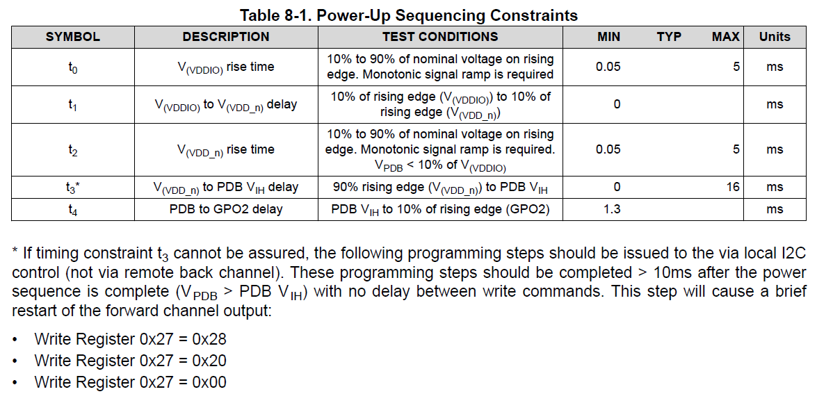
My customer uses our 933 in their ECU board. They are doing the low temperature aging test recently. After one hour aging test, they will restart the board, but they find that one board will appear black screen accidentally. When the fault appears, 0x0c=0x17 while 0x0c=0x15 under normal mode. If we pull PDB pin to low level and then back to high level, the fault will disappear. Could you please help analyze this phenomenon? In addition, 0x0c bit[1]=1 means DES error. Could you please tell me under what circumstances will cause DES Error?

Thanks & Best Regards,

Sherry

  • Hi Sherry,

    CRC errors are caused by accidental changes to the data over the transmission channel. There are many causes for this external disturbance, such as Noise, Reflection, Cross-Talk, etc... For robust operation, there should be no CRC errors. The DES Error bit indicates that there is a CRC error when communicating with the connected deserializer over the Back Channel.

    You need to find the source of the CRC error in your system by looking for possible sources of error in the Schematic and Layout of the board. Also, verify that the Power-Up Sequence of the PDB pin is implemented.

    Best,

    Justin Phan

  • Hi Phan,

    Thanks for your help!

    Yes, they followed the power up sequencing. After power rails stabilizes, they toggled the PDB signal(PDB=0, delay 50ms, PDB=1), delay 50ms, write 0x01=0x31, delay 10ms, write 0x27 = 0x28, 0x27 = 0x20, 0x27 = 0x00. 

    Do you have any other idea for this fault?

    Thanks & best Regards,

    Sherry

  • Hi Sherry,

    For robust operation, the transmission channel should have no errors. Since external disturbances cause CRC errors, then the likely cause for this fault is that there may be an issue with the PCB layout. 

    Did your customer request a Layout Review from TI in the past, in order to verify that the UB933 was properly routed using TI's guidelines? Are you able to find any suspicious points along the DOUT+/- traces from the UB933 to the connector? Can you try a new cable? Are there any issues with the PCB traces on the deserializer board?

    Best,

    Justin Phan

  • You can also evaluate your board using TI's margin analysis tool, which is built-into the Analog Launchpad GUI program. It analyzes how likely it is that the channel would cause errors or loss of lock as a result of system parameters such as cable length, cable type, or layout. In particular, margin analysis is done by looking at all combinations of EQ levels and strobe positions. Systems with a greater number of passing settings have a larger margin.

    See the following App Notes to get started:

    https://www.ti.com/lit/ug/snlu243/snlu243.pdf?ts=1626455027735&ref_url=https%253A%252F%252Fwww.ti.com%252Fproduct%252FDS90UB954-Q1

    https://www.ti.com/lit/an/snla301/snla301.pdf?ts=1626455070101

  • Hi Justin,

    I found that my customer floats GPO2 in their schematic, but our new datasheet requires to add a pull down resistor to GND. Now my customer wants to know why GPO2 can't be floating. Could you please tell me the reason?

    In addition, do we have the internal pull down resistor for GPO2 pin? After power on, we test GPO2 is low level.

    Thanks & Best Regards,

    Sherry

  • Hi Sherry,

    We recommend that you include an external pull-down resistor of at least 40-kOhms to the GPO2 pin. The reason is because we have a Power-Up Sequence that needs to be followed in order for our IC to function properly (See Section 8.1.2 Power-Up Requirements and PDB Pin in the UB933 datasheet). The pull-down resistor is needed at GPO2 in order to ensure that the Power-Up Sequence is not violated due to leakage or other external noise influences. The 40-kOhm recommendation was selected in order to not negatively impact the CLKOUT functionality when this pin is an output. And the GPO2 pin does not have an internal pull-down resistor. 

    Best,

    Justin Phan