Part Number: DS90UB954-Q1
Dear team
The customer working for a second source camera, os02h10.
But we got failed on your data conversion below.
Please help have a look and then provide how to fix the issue.
Thank you so much.
Note:
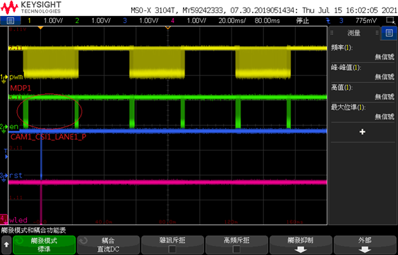
You will see only the head and tail of sensor mipi data converted.
(MDP1 is sensor’s data lane 1 p and CAM1_CSI1_LANE1_P is TI954’s output on data lane 1 p.)
-----------------------------------------------------------------------------------------------------------------------------------
Could you help make sure whether TI954 can not support os02h10_12bit?
Please see the test result of item 3 below:
1.ov2718_12bit:(Preview normally.)
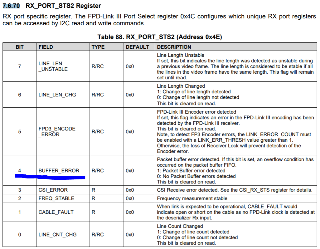
01-01 00:01:06.397 0 0 I __show : 57 0x4e = 0x45
01-01 00:01:08.956 0 0 I __show : 57 0x4e = 0x4
01-01 00:01:10.862 0 0 I __show : 57 0x4e = 0x4
01-01 00:01:12.818 0 0 I __show : 57 0x4e = 0x4
01-01 00:01:14.900 0 0 I __show : 57 0x4e = 0x4
2.ov2718_10bit:(Preview normally.)
07-17 18:15:17.143 0 0 I __show : 57 0x4e = 0x45
07-17 18:15:19.676 0 0 I __show : 57 0x4e = 0x4
07-17 18:15:21.512 0 0 I __show : 57 0x4e = 0x4
07-17 18:15:23.118 0 0 I __show : 57 0x4e = 0x4
07-17 18:15:24.503 0 0 I __show : 57 0x4e = 0x4
3.os02h10_12bit:(No preview.)
01-01 00:02:41.912 0 0 I __show : 57 0x4e = 0x55
01-01 00:02:43.883 0 0 I __show : 57 0x4e = 0x15
01-01 00:02:44.787 0 0 I __show : 57 0x4e = 0x15
01-01 00:02:45.648 0 0 I __show : 57 0x4e = 0x15
01-01 00:02:46.507 0 0 I __show : 57 0x4e = 0x15
4.os02h10_10bit:(No preview.)
07-14 08:23:58.082 0 0 I __show : 57 0x4e = 0x45
07-14 08:23:59.135 0 0 I __show : 57 0x4e = 0x4
07-14 08:24:00.031 0 0 I __show : 57 0x4e = 0x4
07-14 08:24:00.857 0 0 I __show : 57 0x4e = 0x4
07-14 08:24:01.634 0 0 I __show : 57 0x4e = 0x4
Note:
Many thanks
Denny