This thread has been locked.

If you have a related question, please click the "Ask a related question" button in the top right corner. The newly created question will be automatically linked to this question.

TUSB8041: Are there any precautions when applying multi TUSB8041?

Part Number: TUSB8041
Other Parts Discussed in Thread: TUSB8042A, TPS2033, TPS2051

Hi TI experts,

My customer want to apply Two USB hub(TUSB8041) on one board. See block diagram.
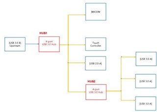
Are there any precautions when applying it like a block diagram? (ex : related to I2C control or Power sequence..)

If there is any document to refer to in the design, please share it with us.

Thanks!

  • Hi,

    Yes, tiered hub designs are pretty common.  Is the customer interested in getting an official USB logo on their product?  If so, in that case they will need to use the latest TUSB8042A device and make sure to implement I2C or SMBUS and mark any permanently connected port as non-removable.  If the customer does not need a USB logo, the TUSB8041 will work and marking permanently connected ports as non-removable is not functionally required.

    Is the customer planning to use I2C or SMBUS with the hubs?  It is optional and used for configuration only.

    Please have the customer take care with the USB_VBUS signal, it is a detection input to the hub and it should not be tied high to a power rail.  It should only be high when an active host is connected.  Either the USB_VBUS of the second hub should be controlled by the PWRON_BATEN of the first hub or connected to the same USB_VBUS source as the first hub.

    Regards,

    JMMN

  • Hi JMMN,

    Thank you for your support!

    The customer has completed the circuit design. Could you review the customer's SCH?

    TUSB8041 SCH_210722.pdf

    Thanks!

  • We will provide feedback by end of week.

    Regards,

    JMMN

  • Hi Downey,

    Schematic feedback:

    1. The customer must connect SS TX to SS RX, SS RX to SS TX between the two hubs.

    2. SMBUSz should be left unconnected if SMBUS is not used.  Enabling SMBUS mode will force the hub to wait in the unconnected state until it is configured by a SMBUS host.  Also do not leave blank EEPROMs connected to the hub if not used, the hub will enter a programming mode.

    3. Power switch polarity can be changed on the hubs rather than using BJTs.  Pullups should be installed on the PWRCTL pins to enable battery charging modes if desired.

    Regards,

    JMMN

  • Hi JMMN,

    Thank you for the comments!

    1. modified.

    2. they not used EEPROM. U27 and U29 is open(DNS). As a result, pin 37, 38 and 39 is floating.

    3. TPS2033 and TPS2051 is Active high products. So they deleted the BJT and connected it with an enable pin. 

    "The PWRCTL_POL is left unconnected which results in active high" described in the datasheet.

    The customer does not use battery charging mode, but configures it as Active high.

    TUSB8041 SCH_210723-2.pdf

    Attached is the revised circuit diagram. Please check it again.

    Thanks!

  • Updated schematic looks ok.

    Regards,

    JMMN

  • Hi JMMN,

    I have 1 more question about 45pin(AUTOENz).

    Automatic mode is not required because no battery charging mode is used. however, customer designed the AUTOENz pin as pull down.

    Should They need to change pull up? Or does it matter if it's pull up or pull down?

    Thanks!

  • Hi Downey,

    The setting of the AUTOENz pin will have no impact if they are not using battery charging.  It can be pulled high / low or left unconnected.

    Regards,

    JMMN