This thread has been locked.

If you have a related question, please click the "Ask a related question" button in the top right corner. The newly created question will be automatically linked to this question.

DP83869HM: Local, remote receiver is not OK

Part Number: DP83869HM
Other Parts Discussed in Thread: DP83869,

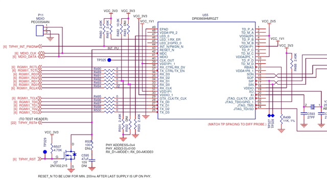
We are using a DP83869 between an AM335x and a 1G SFP.  On the SFP side, the link is coming up. However the SGMII interface to the AM335x is not working.

One thing I notice is that the GEN_STATUS1 register in the DP83869 is 0, indicating "local receiver not okay" and "remote receiver not okay".

First question: What would make them "not okay"?

RGMII_CTRL is 0x00d0, indicating that the transmit and receive clocks are shifted with respect to the data.  I have tried a number of values for DLL_TX_DELAY_CTRL_SL and DLL_RX_DELAY_CTRL_SL in ANA_RGMII_DLL_CTRL.

Second question:  What are the delay values DLL_TX_DELAY_CTRL_SL and DLL_RX_DELAY_CTRL_SL a measurement of (between what and what)?  The description indicates that they affect CLK_90, but CLK_90 does not appear elsewhere in the datasheet.

In case it has an effect:  The 1G SFP wire-side is an RJ45 copper connection going to a switch.  CFG_OPMODE is 1.  Although the switch supports 1G, this link is being negotiated to 100/half.  This causes the AM335x side to set the Tx RGMII clock to 25MHz, while the RX clock from the PHY is at 125 MHz.

Thanks,
    Steve

  • Hello Steve,

    May be there is an error in typing but can you confirm that AM335X is connected via Rgmii and not Sgmii.

    Also when you that SFP side link is coming up, how do you check that? Gen_status1 is for 1000BaseTx (copper connection) and if I understand correctly you are using 1000Base-Fx port.

    You need to select the rgmii_ctrl value based on the Rgmii mode of AM335X. Can you please let me know whether AM335X is running with Rgmii shift mode or Rgmii align mode. I will suggest the required value to be programmed in PHY accordingly.

    --

    Regards,

    Vikram

  • Hi Vikram.

    Yes, the interface is RGMII.

    I am judging link up using the BMSR register.  It is 0x616d.  Until I added support for 10 base T half and 100 base T full to the Linux driver (drivers/net/phy/dp83869.c), the LINK_STS1 bit in that register wasn't getting set after the renegotiation that Linux performs on the way up.

    Does the entirety of the GEN_STATUS1 register only apply to copper connections?  Is that why the REM_RCVR_STATUS and LOC_RCVR_STATUS_1 bits are not being set in my case, and not an indication of a problem?

    As noted, RGMII_CTRL is 0x00d0 so the clocks are shifted.  That comes about due to my indicating that the phy-mode is rgmii-id in the Linux device tree.  That's what led to my second question about what DLL_TX_DELAY_CTRL_SL and DLL_RX_DELAY_CTRL_SL are a measurement of (between what and what).  I have tried a number of settings for those without success and would like to understand exactly what they specify.

        Steve

  • Hello Steve,

    Sorry I could not check your message before the weekend. Yes, rem_rcvr_status and loc_rcvr_status bits are only meant for copper connection and you will not see them going 1 for fiber connection.

    When you use Rgmii shift mode for RX pins of PHY, RX_CLK (at pin of PHY) will get shifted in time with respect to RX_D* and RX_CTRL pins. The delay will be controlled by DLL_RX_DELAY_CTRL_SL. When you use Rgmii shift mode for TX pins of PHY, TX_CLK received at pin will get shifted internally with respect to TX_D* and TX_CTRL received on the PHY pins. This TX delay will be controlled by DLL_TX_DELAY_CTRL_SL. Default values of these bit sets are 'h7 and with value of 'h7 the delay between respective clock and data (as explained above will be ~2ns (i.e. ~90degrees shift for clock period of 8ns and hence these are called clk_90). They can be further skewed with ~250ps of step programmability as mentioned in the datasheet.

    Also make sure that if you are not booting up the PHY in the Rgmii shift mode and rather programming this mode later by programming register x86, then kindly make sure that you also set bits 9 and 8 of this register also 1.

    I hope this clarifies the usage.

    --

    Regards,

    Vikram

  • Hi VIkram.

    I understand the idea of shifting the clock, but am looking for details on the shift to understand how much shift to put in.

    In my case, each connection -- both data and clock -- has approximately the same delay between the AM335x and the PHY.

    Looking a Figure 9 of the DP83869HM datasheet, the transmitter is changing the data on both edges of the clock.  Is the TskewR in that figure the value that is to be placed into DLL_TX_DELAY_CTRL_SL?  That is, the amount to skew the transmit clock so that the edges are in the middle of the data bits instead of when the bits are changing?

    And likewise looking at Figure 10, is the value in DLL_RX_DELAY_CTRL_SL the value TsetupT, the amount to delay the outgoing RX clock so that it ends up in the middle of the data bits?

    This is what I'm getting at when I ask "between what and what" are the delay values measuring.

    Have I got the meanings of the two delays correct?  If not, what are the delays in ANA_RGMII_DLL_CTRL a measurement of.  As I noted, their description says it affects the CLK_90 output, but CLK_90 is not mentioned elsewhere in the datasheet.

    If my above interpretation is correct, there is an issue for transmit.  The AM335x uses a 125 MHz clock when link is negotiated to 1G.  However, when the link is negotiated to 10 or 100 MHz, the RGMII transmit clock is set to just 25 MHz.  As I noted, all of the lines on my board have approximately the same delay.  Therefore, in order to get the clock edges into the middle of the data bits, I would need a delay of half of (1 / 25 MHz)  or 20,000 ps.  However, the DLL_TX_DELAY_CTRL_SL can only be up to 15 x 250 ps or 4000 ps.  So it is not possible to put in a delay appropriate for the connection.

        Steve

  • Hello Steve,

    The delay is between Rx_clk and Rx_D*/Rx_Ctrl (controlled by DLL_RX_DELAY_CTRL_SL) and TX_clk and TX_D*/TX_Ctrl (controlled by DLL_RX_DELAY_CTRL_SL). By programming value 'h7 as explained earlier it shifts by a fixed amount of 2ns (independent of clk frequency : 125MHz and 25MHz). So yes your confusion about clk_"90" is genuine and you may ignore it by taking it as delay between *_Clk and corresponding *_data. And yes, idea is to have maximize the setup and hold time margins (as much as possible)

    --

    Regards,

    Vikram

  • Hi Vikran.

    We seem to be looping.  You are telling me how to specify a delay.  But I'm asking how I determine what delay I need, not how to specify it.

    I think that part of determining how much delay I need is understanding why you want to have any delay "between Rx_clk and Rx_D*/Rx_Ctrl".  Is it to get the clock edges in the middle of the data bits as I guessed?  Or something else?  I don't think I can figure out what delay is required until I know what the delay is trying to achieve.

    Is my above calculation of what delay I need correct?  If so, I need 20ns of delay which is more than you can set in the register.

        Steve

  • Hi Steve,

    Sorry if I was not clear the last time and yes Rgmii delay setting can get a little confusing. But if you refer to Rgmii standard, you will see that the delay and required setup/hold margins have been defined for modes without delay and modes without delay introduction. But just to simplify things and provide you direct answers :

    1. For 4ns of clock high width (125MHz frequency), ideally we will like to place clock at 2ns from data transition to maximize both setup and hold margins.

    2. For 20ns of clock high width (25MHz frequency), ideally we will like to place clock at 20ns from data transition to maximize both setup and hold margins.

    3. Our PHY can provide delay of 2ns and this can be further increased or decreased in steps of 250ps for some range. So 20ns is not achievable but Rgmii standard requirement is 1ns of setup time margin, so shifting by 2ns meets that with margin.

    4. Margins gained by shifting of clk with respect to data will also be eaten by your board skews and skews between data-clk from the transmitter side.

    I hope these points above will help you understand the delay requirement/concept further. I will also encourage you to go through Rgmii standard for further details if required.

    --

    Regards,

    Vikram

  • Thanks for the info Vikram.  There turned out to be a number of problems.

    First, there's a bug in the Linux driver for the DP83869.  Auto-negotiation results were determined by the generic PHY routine genphy_read_lpa(), but that uses MII_STAT1000 a.k.a. GEN_STATUS1.  However, as you note above GEN_STATUS1 is not valid for fiber connections.  We had to update the driver to use the custom FX_STS and FX_LPABL registers instead.  That allows the cpsw driver to see the link at 1G and therefore set up an RGMII connection for 1G (at 125MHz).

    Second, the problem with 100M connections seems to be in the SFP.  It looks like the ones we have support only 1G connections, not 10M/100M.  With the correct ones and the cpsw driver using 25 MHz for RGMII transmit due to the lower speed link, I'm not sure if there will remain issues on the RGMII bus.  We will see.

    Finally, through experimentation it was determined that the minimum values for delay on the RGMII bus work best in our case.

    Thanks for your help.

        Steve

  • Hello Steve,

    First of all thanks for the update and very sorry for the botheration because of suspected weakness in driver. I have reported it to the team to verify the observations.

    --

    Regards,

    Vikram