Part Number: SN75HVD10
RS485 Operation
Part Used:SN75HVD10
Date: 2021-0-27
Issue:
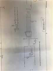
We are using the SN5HVD10 which is a 3.3V RS485 Transceiver for our RS485 communication. The schematic design is very simple as I show in one of the picutres. There
is a 10K pullup on pin 1 (R). The device is powered from a switching regulator at 3.3V. I have a jumper in place to add the 100 ohm termination. The DE and RE lines
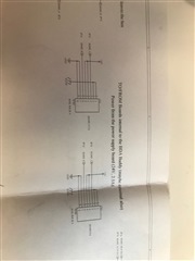
are directly connected to my microprocessor for data direction control. The RS485 A and B lines are duplicated on two RJ45 connectors that also contain power and
ground for the board. We want the ability to hot switch the boards. According to the data sheet we should be able to hot switch these transceivers.
In my test setup I have two boards communicating with eachother. This is a half-duplex configuration.
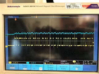
If I start with two new RS485 chips on board1 and board2. I checked the signal on board1 for A and B without board2 connected. Looking at A and B the signals generated
by board1 look good. The waveforms are about 3Vpp and they are what I would expect for a differential signal. This is shown in one of the pictures. I cycled power to
board1 numerous times and signal was fine.
I then hot connected the RJ45 cable to board2 and the signal on A and B looked the same as mentioned above.
In one case I hot switched the board about 10 times and the signals matched the description above.
On the 11th time (this is not significant - it changes) the signal on A looked the same but the signal on B is about 1/4 the amplitude of the signal on A. The signal
is still differential and surprisingly enough the Receiver Input worked. The microprocessor on the receiving side actually worked under these circumstances. I guess
the transceiver is still meeting the 200mV threshold necessary for the communication to work but it's obviously not correct.
I have also seen a case where I experienced the same conditions described above but eventaully B failed where B appeared at 1/4 of the amplitude of A but
it was in phase with A which means the differential signal was not working and the communication failed.
Most of the time I saw the RS485 failure on board1 after connecting board2 but I have seen board2 fail also.
I've replaced numerous chips trying to troubleshoot this issue.
We don't have ESD protection on the circuit. We are not exposing this signal to the outside world. We are within an enclosure but we wanted to be able to hot switch
the boards within the enclosure.
Board1 and board2 are different but the RS485 circuit is exactly the same.
I'm sending a picture of the RS485 circuit and the connector. I can't send the entire schematic. We are using an OKI-78SR-3.3/1.5 switching regulator for 3.3V on the
board. The +24V on the board which is coming from the RJ45 connectors is the input source for the OKI... part.
We are using a CAT5 or CAT6 cable between the boards.
If I don't hotswitch the boards and I perform a controlled power up I really can't recall seeing a problem. Once the system is operational we have never seen a
problem. It has something to do with the hotswitching. It's interesting to me that board1 seems to go bad after I power up board2.
I looked at the power up and power down sequence and monitored A and B during those transitions. I see B having a pulse going down to -6V for about 800ms on power up
but that seems to happen on every power up and the communication was still working.
I really don't think it's a static issue since it's not cold and it's fairly humid in my testing environment although I can't see what could be causing this problem.
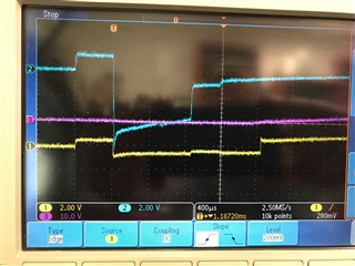
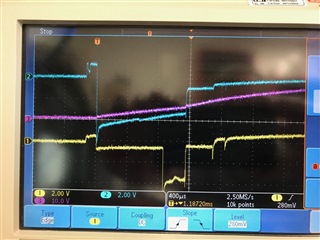
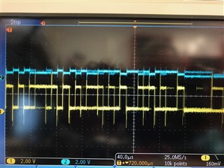
Below are some scope pictures. The first scope picture show A (yellow) and B (blue) as an expected RS485 differential signal. After hot switching one of the boards a number of times I'm seeing the B at 1/4 the amplitude of A as is shown in the second and third pictures. The other two pictures are the sections of the schematic for the design of the circuit involving the SN75HVD10.
Thanks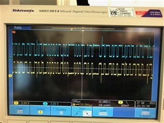
Thanks