This thread has been locked.

If you have a related question, please click the "Ask a related question" button in the top right corner. The newly created question will be automatically linked to this question.

TCA9517: With VCCA > VCCB, translation doesn't work.

Part Number: TCA9517

Hi there,

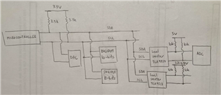
I am currently working with a TCA9517DGKRQ1 (TCA9517DGKRQ1 Texas Instruments | Integrated Circuits (ICs) | DigiKey) part and I have VCCB and VCCA set to 3.3 V and 5 V, respectively. The VCCB SDA/SCL lines are connected to the microcontroller I2C lines and the VCCA SDA/SCL lines are connected to some ADCs.

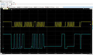
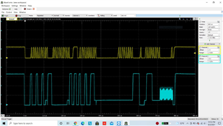
Now, when I tried acquiring some data from the ADCs via I2C, nothing happens. I have probed the VCCB SDA/SCL lines (pulled to 3.3 V via a resistor) and I do see the I2C clock and data signals; however, when I probe the VCCA SDA/SCL lines (pulled to 5 V via a resistor) and I do NOT see the clock and data signals. Can you help me understand why? Based on what I'm observing, it seems that VCCA supply cannot be greater and VCCB supply even though the datasheet does not confirm that. Can you please provide an insight on this?

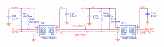
For reference, the below information tells you how everything is connected on my board

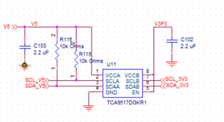
VCCA (pin 1) = 5 V, decoupling capacitor = 2.2 uF

SCLA (pin 2) = Pulled up to 5 V via 10 kOhms

SDAA (pin 3) = Pulled up to 5 V via 10 kOhms 

GND (pin 4) = ground

EN (pin 5) = Shorted to 3.3 V

SDAB (pin 6) = Pulled up to 3.3 V via 3.3 kOhms

SCLA (pin 7) = Pulled up to 3.3 V via 3.3 kOhms

VCCB (pin 8) = 3.3 V, decoupling capacitor = 2.2 uF

Thanks,

Alex

  • So the main question I'd like to understand is, does VCCB needs to be greater than VCCA to function properly? Also, for another reference, the marking on the IC is TI 07 1N2

  • Alexandre,

    An engineer has been notified of your post and will respond by the end of the day tomorrow CST.

    Regards,

    Eric Hackett 

  • Hi Alex,

    In order for a signal to propagate from the B-side to the A-side the logic low on the B side has to be below the VILC threshold which for this device is 0.4V. This is because this device features a static voltage offset on the B side. Can you make sure that the device on the B side has a VOL less than 0.4V.

    There is no supply requirements on this device so it doesn't matter which supply is larger than the other.

    If this doesn't work can you provide scope shots and a schematic of your setup. For the scope shots I want to see SDAB, SDAA, VCCA, and VCCB.

    Best,

    Chris

  • Thank you for your response.

    The microcontroller I2C lines are connected to the level shifter B side. And the microcontroller does drive the B side below 400 mV. What I'm seeing is that, in idle mode (no data is transmitted), the B side is pulled to 3.3 V (I checked both SDAB and SCLB and they indeed show 3.3 V). I would expect the SDAA and SCLA lines to be pulled to 5 V, but they show 1 V. Any idea why?

  • Alex,

    Can you provide a schematic so I can double check your setup? 

    What device is connected to the A side? Is the device connected to the A side trying to drive the bus low?

    Best,

    Chris

  • First figure shows the set up for the level shifter. On the A side, I have 4 ADCs (ADS1115BQDGSRQ1). The second figure gives you an example how I connected the I2C lines of the A-side with the I2C of the ADCs


  • I don't support these ADC devices so I am not entirely sure how it works. Can you disconnect all the ADC devices from the TCA9517 and check to see if the A side gets pulled up?

    Then you can add in the ADC devices one by one and see which device is pulling the bus lines low.

    Best,

    Chris

  • Chris, 

    Below is a diagram of the PCB I'm currently working with

    The ADC block represents 4 ADCs.

    Now, I have run a couple tests on one of the ADCs. So, the first test I ran I just simply shorted analog input of the ADC to ground. And I get the following on the I2C bus

    The yellow signal is the clock from the A-side of the bottom level shifter (B-side to 3.3 V and A-side to 1.2 V). The blue signal is the data from the 3.3 V bus that the microcontroller is driving. Also, the zero logic level from the microcontroller is not pulled to zero (~0.5 V). Would you have any insight why that happens and what would the remedy be?

    On the second test, I kept the analog input of the ADC opened; and I get the following

    You can notice an oscillation on the data line and I'm seeing that quite often. Prior to this current board, I was working with another PCB that had only one level shifter (B-side pulled to 3.3 V and A-side pulled to 1.8 V), and I was not seeing that problem. On the current board, however, I have two level shifters (the new addition has B-side pulled to 3.3 V and A-side pulled to 5 V) and this oscillating problem started occurring on both SDA and SCL lines. Would you have any idea what could be causing this oscillation and how to fix it? 

  • Hi Alex,

    For your two TCA9517's in parallel are they connected B-side to B-side? It looks like it from my point of view. This is not allowed on this device since it comes with a static voltage offset on the B-side of the device. You cannot connect two static voltage offset devices in parallel together. You will have to flip one of the devices and since there is so supply requirements with this device you should have no issues.

    My next concern is the bus capacitance of all those devices connected in parallel on the B-side of the device. Do you know what your bus capacitance is and have you done the required pull up resistor calculations

    Best,

    Chris

  • Yes, currently both TCA9517's have their B-side connected in parallel. So they might be the cause of the problem I'm having. Now, when I flip the devices, the A-side one will be in parallel with the B-side of the other. Would that be OK?

  • Yes that is the correct setup for this device. Let me know if that solves your issue.

    Best,

    Chris

  • Having both level shifters with both B-side in parallel was the problem. Once I removed one of them, everything started working fine. I'm setting the circuit as the following

    This should work well. Please let me know.

    Thanks,

    Alex

  • Alex,

    This should work. Once again make sure to check that your pull up resistance is correct. If your VOL is too high that means that your pull up resistor is too small. If your rising edge is too slow that means that your pull up resistor is too large.

    If any of these answers solved your problem don't forget to hit the button. It will automatically close out the thread.

    Best,

    Chris

  • Thanks for the help, Chris. I appreciate it!